D-Link DGS-3200-10 Product Manual - Page 61
RMON, CPU Filter L3 Control Packet Settings, Single IP Management
 |
UPC - 790069306310
View all D-Link DGS-3200-10 manuals
Add to My Manuals
Save this manual to your list of manuals |
Page 61 highlights
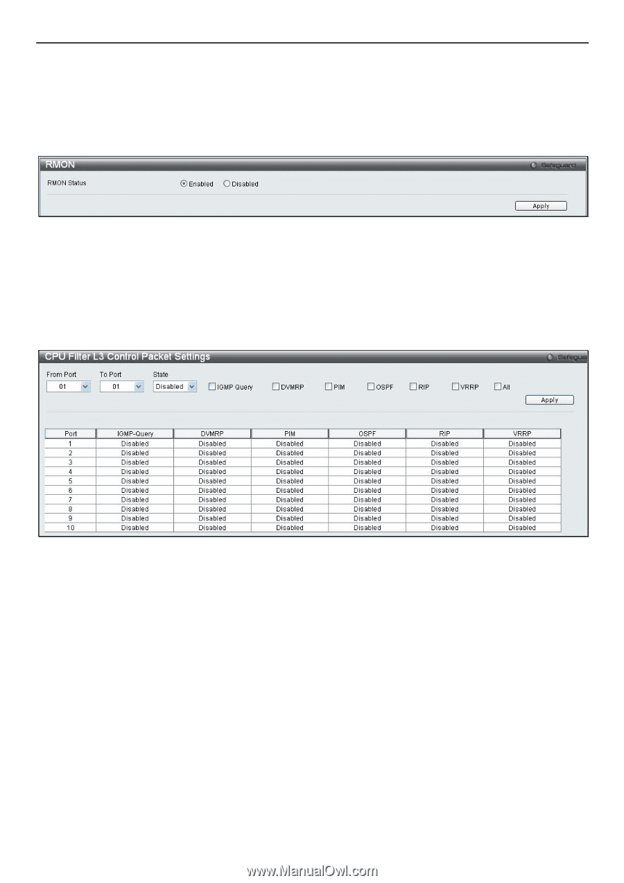
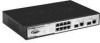
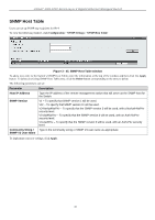
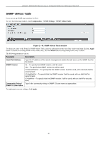
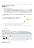
xStack® DGS-3200 Series Layer 2 Gigabit Ethernet Managed Switch RMON Users can enable and disable remote monitoring (RMON) status for the SNMP function on the Switch. In addition, RMON Rising and Falling Alarm Traps can be enabled and disabled. To view the following window, click Configuration > SNMP Settings > RMON: Figure 2 - 49. RMON window To enable or disable RMON for SNMP, use the radio buttons. Click Apply when finished. CPU Filter L3 Control Packet Settings Users can discard and display Layer 3 control packets sent to the CPU from specific ports. To view the following window, click Configuration > CPU Filter L3 Control Packet Settings: Figure 2 - 50. CPU Filter L3 Control Packet Settings window To set CPU filter Layer 3 control packet settings on the Switch, use the From Port and To Port drop-down menus to select the desired port range, change the State to Enabled, and tick the desired Layer 3 categories (IGMP Query, DVMRP, PIM, OSPF, RIP, VRRP, or All). Click Apply when finished. Single IP Management Simply put, D-Link Single IP Management is a co ncept that will stack switches together over Ethernet instead of using stacking ports or modules. There are some advantages in implementing the "Single IP Management" feature: 1. SIM can si mplify management o f sm all w orkgroups or wiring cl osets whi le scal ing t he net work t o han dle i ncreased bandwidth demand. 2. SIM can reduce the number of IP address needed in your network. 3. SIM can eliminate any specialized cables for stacking connectivity and remove the distance barriers that typically limit your topology options when using other stacking technology. Switches using D-Link Single IP Management (labeled here as SIM) must conform to the following rules: SIM is a n optional feature on the Switch a nd can easily be enabled or disabled through the Command Line Interface or Web Interface. SIM grouping has no effect on the normal operation of the Switch in the user's network. 48
-
 1
1 -
2
-
3
-
4
-
5
-
6
-
7
-
8
-
9
-
10
-
11
-
12
-
13
-
14
-
15
-
16
-
17
-
18
-
19
-
20
-
21
-
22
-
23
-
24
-
25
-
26
-
27
-
28
-
29
-
30
-
31
-
32
-
33
-
34
-
35
-
36
-
37
-
38
-
39
-
40
-
41
-
42
-
43
-
44
-
45
-
46
-
47
-
48
-
49
-
50
-
51
-
52
-
53
-
54
-
55
-
 56
56 -
 57
57 -
 58
58 -
 59
59 -
 60
60 -
 61
61 -
 62
62 -
 63
63 -
 64
64 -
 65
65 -
 66
66 -
67
-
68
-
69
-
70
-
71
-
72
-
73
-
74
-
75
-
76
-
77
-
78
-
79
-
80
-
81
-
82
-
83
-
84
-
85
-
86
-
87
-
88
-
89
-
90
-
91
-
92
-
93
-
94
-
95
-
96
-
97
-
98
-
99
-
100
-
101
-
102
-
103
-
104
-
105
-
106
-
107
-
108
-
109
-
110
-
111
-
112
-
113
-
114
-
115
-
116
-
117
-
118
-
119
-
120
-
121
-
122
-
123
-
124
-
125
-
126
-
127
-
128
-
129
-
130
-
131
-
132
-
133
-
134
-
135
-
136
-
137
-
138
-
139
-
140
-
141
-
142
-
143
-
144
-
145
-
146
-
147
-
148
-
149
-
150
-
151
-
152
-
153
-
154
-
155
-
156
-
157
-
158
-
159
-
160
-
161
-
162
-
163
-
164
-
165
-
166
-
167
-
168
-
169
-
170
-
171
-
172
-
173
-
174
-
175
-
176
-
177
-
178
-
179
-
180
-
181
-
182
-
183
-
184
-
185
-
186
-
187
-
188
-
189
-
190
-
191
-
192
-
193
-
194
-
195
-
196
-
197
-
198
-
199
-
200
-
201
-
202
-
203
-
204
-
205
-
206
-
207
-
208
-
209
-
210
-
211
-
212
-
213
-
214
-
215
-
216
-
217
-
218
-
219
-
220
-
221
-
222
-
223
-
224
-
225
-
226
-
227
-
228
-
229
-
230
-
231
-
232
-
233
-
234
-
235
-
236
-
237
-
238
-
239
-
240
-
241
-
242
-
243
-
244
-
245
-
246
-
247
-
248
-
249
-
250
-
251
-
252
-
253
-
254
-
255
-
256
-
257
-
258
-
259
-
260
-
261
-
262
-
263
-
264
-
265
-
266
-
267
-
268
-
269
-
270
-
271
-
272
-
273
-
274
-
275
-
276
-
277
-
278
-
279
-
280
-
281
-
282
-
283
-
284
-
285
-
286
-
287
-
288
-
289
-
290
-
291
-
292
-
293
-
294
-
295
-
296
-
297
-
298
-
299
-
300
-
301
-
302
 |
 |