D-Link DGS-3200-10 Product Manual - Page 127
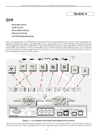
Understanding QoS, A1, B1, C1, D1, E1, F1, G1, H1, A2, B2, C2, D2, E2, F2, G2, A3, B3, C3, D3, E3, F3
 |
UPC - 790069306310
View all D-Link DGS-3200-10 manuals
Add to My Manuals
Save this manual to your list of manuals |
Page 127 highlights
xStack® DGS-3200 Series Layer 2 Gigabit Ethernet Managed Switch see if it h as the prop er id entifying tag . Then th e us er ma y f orward th ese ta gged packets to designated classes of se rvice on th e Switch where they will be emptied, based on priority. For example, let's say a user wishes to have a vi deo conference between two remotely set computers. The administrator can add priority tags t o the video packets being sent out, utilizing the A ccess Profile c ommands. Then, on t he re ceiving e nd, the administrator instructs the Switch to examine packets for this tag, acquires the tagged packets and maps them to a class queue on the Switch. Then in turn, th e ad ministrator will set a p riority fo r th is queu e so t hat will b e e mptied before an y o ther p acket is forwarded. This results in t he end user receiving all packet s sent as quickly as po ssible, thus pri oritizing the queue and allowing for an uninterrupted stream of packets, which optimizes the use of bandwidth available for the video conference. Understanding QoS The Switch supports 802.1p priority queuing. The Switch has eight priority q ueues. These prior ity queues a re numbered from 7 (Class 7) - the h ighest priority q ueue - to 0 (Class 0) - the lowest priority queue. The eight priority tags specified in IEEE 802.1p (p0 to p7) are mapped to the Switch's priority queues as follows: Priority 0 is assigned to the Switch's Q2 queue. Priority 1 is assigned to the Switch's Q0 queue. Priority 2 is assigned to the Switch's Q1 queue. Priority 3 is assigned to the Switch's Q3 queue. Priority 4 is assigned to the Switch's Q4 queue. Priority 5 is assigned to the Switch's Q5 queue. Priority 6 is assigned to the Switch's Q6 queue. Priority 7 is assigned to the Switch's Q7 queue. For st rict priority-based scheduling, any packets resid ing in th e h igher priority cla sses of serv ice are transmitted first. Mu ltiple strict priority classes of service are emptied based on their priority tag s. Only when these classes are empty, are packets of lower priority transmitted. For weighted round-robin queuing, the number of packets sent from each priority queue depends upon the assigned weight. For a configuration of eight CoS queues, A~H with their res pective weight value: 8~1, the packets are sent in the following sequence: A1, B1, C1, D1, E1, F1, G1, H1, A2, B2, C2, D2, E2, F2, G2, A3, B3, C3, D3, E3, F3, A4, B4, C4, D4, E4, A5, B5, C5, D5, A6, B6, C6, A7, B7, A8, A1, B1, C1, D1, E1, F1, G1, H1. For weighted round-robin queuing, if each CoS queue has the same weight value, then each CoS queue has an equal opportunity to send packets just like round-robin queuing. For weighted round-robin queuing, if t he weight for a C oS is set to 0, t hen it will co ntinue processing the packets from this CoS until there are no more packets for this CoS. The other CoS queues that have been given a nonzero value, and depending upon the weight, will follow a common weighted round-robin scheme. Remember that the Switch has seven configurable priority queues (and seven Classes of Service) for each port on the Switch. NOTICE: The Switch contains eight classes of service for each port on the Switch. One of these classes is reserved for internal use on the Switch and is therefore not configurable. All references in the following section regarding classes of service will refer to only the seven classes of service that may be used and configured by the administrator. 114
-
 1
1 -
2
-
3
-
4
-
5
-
6
-
7
-
8
-
9
-
10
-
11
-
12
-
13
-
14
-
15
-
16
-
17
-
18
-
19
-
20
-
21
-
22
-
23
-
24
-
25
-
26
-
27
-
28
-
29
-
30
-
31
-
32
-
33
-
34
-
35
-
36
-
37
-
38
-
39
-
40
-
41
-
42
-
43
-
44
-
45
-
46
-
47
-
48
-
49
-
50
-
51
-
52
-
53
-
54
-
55
-
56
-
57
-
58
-
59
-
60
-
61
-
62
-
63
-
64
-
65
-
66
-
67
-
68
-
69
-
70
-
71
-
72
-
73
-
74
-
75
-
76
-
77
-
78
-
79
-
80
-
81
-
82
-
83
-
84
-
85
-
86
-
87
-
88
-
89
-
90
-
91
-
92
-
93
-
94
-
95
-
96
-
97
-
98
-
99
-
100
-
101
-
102
-
103
-
104
-
105
-
106
-
107
-
108
-
109
-
110
-
111
-
112
-
113
-
114
-
115
-
116
-
117
-
118
-
119
-
120
-
121
-
 122
122 -
 123
123 -
 124
124 -
 125
125 -
 126
126 -
 127
127 -
 128
128 -
 129
129 -
 130
130 -
 131
131 -
 132
132 -
133
-
134
-
135
-
136
-
137
-
138
-
139
-
140
-
141
-
142
-
143
-
144
-
145
-
146
-
147
-
148
-
149
-
150
-
151
-
152
-
153
-
154
-
155
-
156
-
157
-
158
-
159
-
160
-
161
-
162
-
163
-
164
-
165
-
166
-
167
-
168
-
169
-
170
-
171
-
172
-
173
-
174
-
175
-
176
-
177
-
178
-
179
-
180
-
181
-
182
-
183
-
184
-
185
-
186
-
187
-
188
-
189
-
190
-
191
-
192
-
193
-
194
-
195
-
196
-
197
-
198
-
199
-
200
-
201
-
202
-
203
-
204
-
205
-
206
-
207
-
208
-
209
-
210
-
211
-
212
-
213
-
214
-
215
-
216
-
217
-
218
-
219
-
220
-
221
-
222
-
223
-
224
-
225
-
226
-
227
-
228
-
229
-
230
-
231
-
232
-
233
-
234
-
235
-
236
-
237
-
238
-
239
-
240
-
241
-
242
-
243
-
244
-
245
-
246
-
247
-
248
-
249
-
250
-
251
-
252
-
253
-
254
-
255
-
256
-
257
-
258
-
259
-
260
-
261
-
262
-
263
-
264
-
265
-
266
-
267
-
268
-
269
-
270
-
271
-
272
-
273
-
274
-
275
-
276
-
277
-
278
-
279
-
280
-
281
-
282
-
283
-
284
-
285
-
286
-
287
-
288
-
289
-
290
-
291
-
292
-
293
-
294
-
295
-
296
-
297
-
298
-
299
-
300
-
301
-
302
 |
 |