D-Link DGS-3200-10 Product Manual - Page 223
Time Range Settings, Apply, Show Details, Access, Rule List, ACL > Time Range Settings
 |
UPC - 790069306310
View all D-Link DGS-3200-10 manuals
Add to My Manuals
Save this manual to your list of manuals |
Page 223 highlights
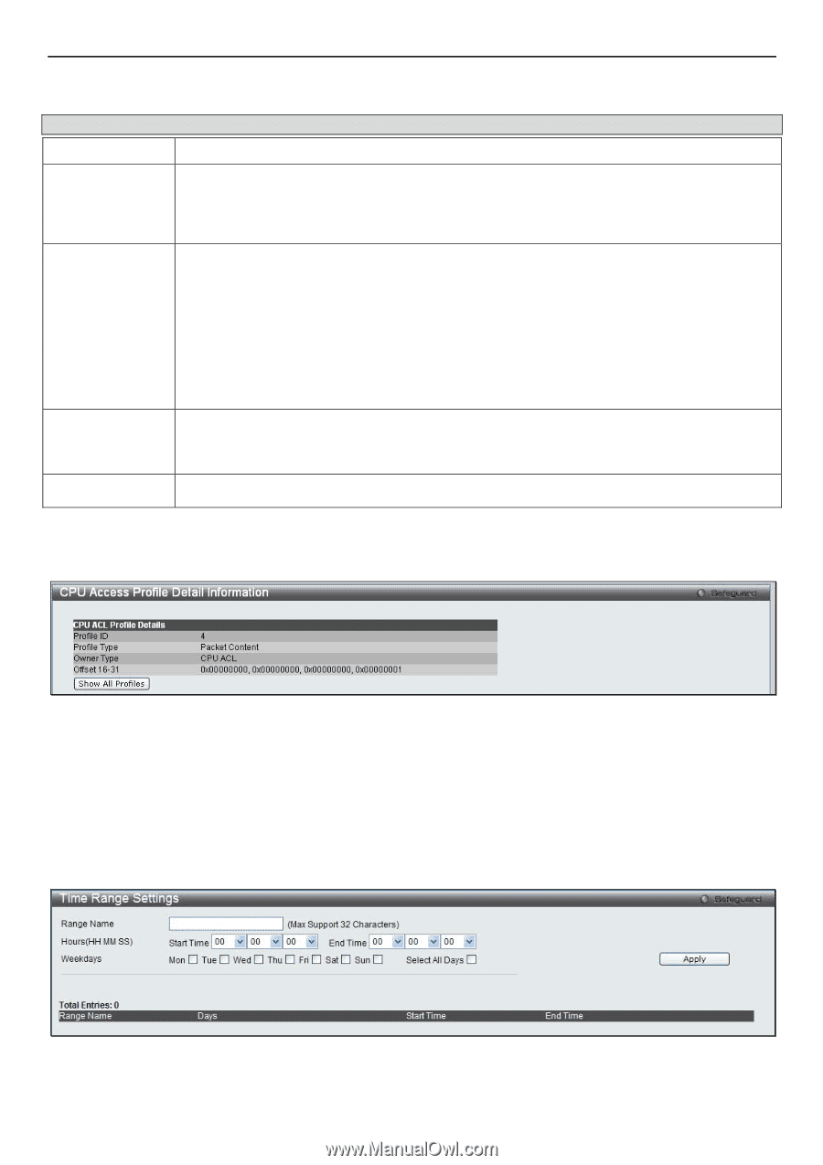
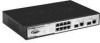
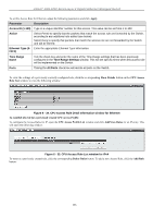
xStack® DGS-3200 Series Layer 2 Gigabit Ethernet Managed Switch To set the Access Rule for Packet Content, adjust the following parameters and click Apply. Parameter Description Access ID (1-100) Type in a unique identifier number for this access. This value can be set from 1 to 100. Action Select Permit to specify that the packets that match the access rule are forwarded by the Switch, according to any additional rule added (see below). Select Deny to specify that packets that match the access rule are not forwarded by the Switch and will be filtered. Offset This field will instruct the Switch to mask the packet header beginning with the offset value specified: Offset 0-15 - Enter a value in hex form to mask the packet from the beginning of the packet to the 15th byte. Offset 16-31 - Enter a value in hex form to mask the packet from byte 16 to byte 31. Offset 32-47 - Enter a value in hex form to mask the packet from byte 32 to byte 47. Offset 48-63 - Enter a value in hex form to mask the packet from byte 48 to byte 63. Offset 64-79 - Enter a value in hex form to mask the packet from byte 64 to byte 79. Time Range Name Tick the check box and enter the name of the Time Range settings that has been previously configured in the Time Range Settings window. This will set specific times when this access rule will be implemented on the Switch. Ports Ticking the All Ports check box will denote all ports on the Switch. To view the settings of a previously correctly configured rule, click the co rresponding Show Details button on th e CPU Access Rule List window to view the following window: Figure 6 - 43. CPU Access Rule Detail Information window for Packet Content Time Range Settings In conjunction with t he Access Profile feature, the time range settings determine a startin g point and an ending point, based on days of th e week, when an Access Pro file co nfiguration will b e en abled on th e Swit ch. Once con figured h ere, t he ti me ran ge settings are to be applied to an access profile rule using the Access Profile table. The user may enter up to 64 time range entries on the Switch. To view the following window, click ACL > Time Range Settings: Figure 6 - 44. Time Range Settings window 210
-
 1
1 -
2
-
3
-
4
-
5
-
6
-
7
-
8
-
9
-
10
-
11
-
12
-
13
-
14
-
15
-
16
-
17
-
18
-
19
-
20
-
21
-
22
-
23
-
24
-
25
-
26
-
27
-
28
-
29
-
30
-
31
-
32
-
33
-
34
-
35
-
36
-
37
-
38
-
39
-
40
-
41
-
42
-
43
-
44
-
45
-
46
-
47
-
48
-
49
-
50
-
51
-
52
-
53
-
54
-
55
-
56
-
57
-
58
-
59
-
60
-
61
-
62
-
63
-
64
-
65
-
66
-
67
-
68
-
69
-
70
-
71
-
72
-
73
-
74
-
75
-
76
-
77
-
78
-
79
-
80
-
81
-
82
-
83
-
84
-
85
-
86
-
87
-
88
-
89
-
90
-
91
-
92
-
93
-
94
-
95
-
96
-
97
-
98
-
99
-
100
-
101
-
102
-
103
-
104
-
105
-
106
-
107
-
108
-
109
-
110
-
111
-
112
-
113
-
114
-
115
-
116
-
117
-
118
-
119
-
120
-
121
-
122
-
123
-
124
-
125
-
126
-
127
-
128
-
129
-
130
-
131
-
132
-
133
-
134
-
135
-
136
-
137
-
138
-
139
-
140
-
141
-
142
-
143
-
144
-
145
-
146
-
147
-
148
-
149
-
150
-
151
-
152
-
153
-
154
-
155
-
156
-
157
-
158
-
159
-
160
-
161
-
162
-
163
-
164
-
165
-
166
-
167
-
168
-
169
-
170
-
171
-
172
-
173
-
174
-
175
-
176
-
177
-
178
-
179
-
180
-
181
-
182
-
183
-
184
-
185
-
186
-
187
-
188
-
189
-
190
-
191
-
192
-
193
-
194
-
195
-
196
-
197
-
198
-
199
-
200
-
201
-
202
-
203
-
204
-
205
-
206
-
207
-
208
-
209
-
210
-
211
-
212
-
213
-
214
-
215
-
216
-
217
-
 218
218 -
 219
219 -
 220
220 -
 221
221 -
 222
222 -
 223
223 -
 224
224 -
 225
225 -
 226
226 -
 227
227 -
 228
228 -
229
-
230
-
231
-
232
-
233
-
234
-
235
-
236
-
237
-
238
-
239
-
240
-
241
-
242
-
243
-
244
-
245
-
246
-
247
-
248
-
249
-
250
-
251
-
252
-
253
-
254
-
255
-
256
-
257
-
258
-
259
-
260
-
261
-
262
-
263
-
264
-
265
-
266
-
267
-
268
-
269
-
270
-
271
-
272
-
273
-
274
-
275
-
276
-
277
-
278
-
279
-
280
-
281
-
282
-
283
-
284
-
285
-
286
-
287
-
288
-
289
-
290
-
291
-
292
-
293
-
294
-
295
-
296
-
297
-
298
-
299
-
300
-
301
-
302
 |
 |