D-Link DGS-3200-10 Product Manual - Page 37
DHCP/BOOTP Relay Interface Settings, DHCP Local Relay Settings - 24 e
 |
UPC - 790069306310
View all D-Link DGS-3200-10 manuals
Add to My Manuals
Save this manual to your list of manuals |
Page 37 highlights
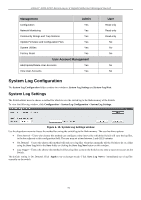
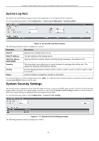
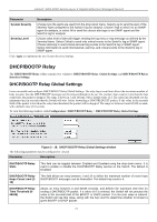
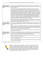
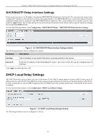
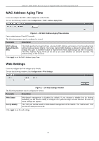
xStack® DGS-3200 Series Layer 2 Gigabit Ethernet Managed Switch DHCP/BOOTP Relay Interface Settings Users can set up a server, by IP address, for relaying DHCP/BOOTP information to the Switch. Th e user may enter a previ ously configured IP interface on the Switch th at will b e con nected d irectly to the DHCP/BOOTP serv er u sing this wind ow. Prop erly configured settings will be di splayed i n the DHCP/BOOTP Re lay Interface Table at t he bottom of t he window, once the user clicks the Apply button. The user may add up to four server IPs per IP interface on the Switch. Entries may be deleted by clicking the corresponding Delete button. To view the following window, click Configuration > DHCP/BOOTP Relay > DHCP/BOOTP Relay Interface Settings: Figure 2 - 20. DHCP/BOOTP Relay Interface Settings window The following parameters may be configured or viewed: Parameter Description Interface Server IP The IP interface on the Switch that will be connected directly to the Server. Enter the IP address of the DHCP/BOOTP server. Up to four server IPs can be configured per IP Interface. Click Apply to include this Server IP. DHCP Local Relay Settings The DHCP local relay settin gs allows t he user to add optio n 82 in to DHCP request packets wh en t he DHCP clien t g ets an IP address from the same VLAN. If the DHCP local relay settings are not configured, the Switch will flood the packets to the VLAN. In order to add option 82 into the DHCP request packets, the DHCP local relay settings and the state of the Global VLAN need to be enabled. To view the following window, click Configuration > DHCP Local Relay Settings: Figure 2 - 21. DHCP Local Relay Settings window The following parameters may be configured or viewed: 24
-
 1
1 -
2
-
3
-
4
-
5
-
6
-
7
-
8
-
9
-
10
-
11
-
12
-
13
-
14
-
15
-
16
-
17
-
18
-
19
-
20
-
21
-
22
-
23
-
24
-
25
-
26
-
27
-
28
-
29
-
30
-
31
-
 32
32 -
 33
33 -
 34
34 -
 35
35 -
 36
36 -
 37
37 -
 38
38 -
 39
39 -
 40
40 -
 41
41 -
 42
42 -
43
-
44
-
45
-
46
-
47
-
48
-
49
-
50
-
51
-
52
-
53
-
54
-
55
-
56
-
57
-
58
-
59
-
60
-
61
-
62
-
63
-
64
-
65
-
66
-
67
-
68
-
69
-
70
-
71
-
72
-
73
-
74
-
75
-
76
-
77
-
78
-
79
-
80
-
81
-
82
-
83
-
84
-
85
-
86
-
87
-
88
-
89
-
90
-
91
-
92
-
93
-
94
-
95
-
96
-
97
-
98
-
99
-
100
-
101
-
102
-
103
-
104
-
105
-
106
-
107
-
108
-
109
-
110
-
111
-
112
-
113
-
114
-
115
-
116
-
117
-
118
-
119
-
120
-
121
-
122
-
123
-
124
-
125
-
126
-
127
-
128
-
129
-
130
-
131
-
132
-
133
-
134
-
135
-
136
-
137
-
138
-
139
-
140
-
141
-
142
-
143
-
144
-
145
-
146
-
147
-
148
-
149
-
150
-
151
-
152
-
153
-
154
-
155
-
156
-
157
-
158
-
159
-
160
-
161
-
162
-
163
-
164
-
165
-
166
-
167
-
168
-
169
-
170
-
171
-
172
-
173
-
174
-
175
-
176
-
177
-
178
-
179
-
180
-
181
-
182
-
183
-
184
-
185
-
186
-
187
-
188
-
189
-
190
-
191
-
192
-
193
-
194
-
195
-
196
-
197
-
198
-
199
-
200
-
201
-
202
-
203
-
204
-
205
-
206
-
207
-
208
-
209
-
210
-
211
-
212
-
213
-
214
-
215
-
216
-
217
-
218
-
219
-
220
-
221
-
222
-
223
-
224
-
225
-
226
-
227
-
228
-
229
-
230
-
231
-
232
-
233
-
234
-
235
-
236
-
237
-
238
-
239
-
240
-
241
-
242
-
243
-
244
-
245
-
246
-
247
-
248
-
249
-
250
-
251
-
252
-
253
-
254
-
255
-
256
-
257
-
258
-
259
-
260
-
261
-
262
-
263
-
264
-
265
-
266
-
267
-
268
-
269
-
270
-
271
-
272
-
273
-
274
-
275
-
276
-
277
-
278
-
279
-
280
-
281
-
282
-
283
-
284
-
285
-
286
-
287
-
288
-
289
-
290
-
291
-
292
-
293
-
294
-
295
-
296
-
297
-
298
-
299
-
300
-
301
-
302
 |
 |
