D-Link DGS-3200-10 Product Manual - Page 21
Serial Port Settings, IP Address, Serial Port Settings window, Baud Rate, Auto Logout - user manual
 |
UPC - 790069306310
View all D-Link DGS-3200-10 manuals
Add to My Manuals
Save this manual to your list of manuals |
Page 21 highlights
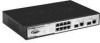
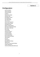
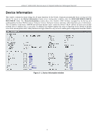
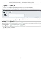
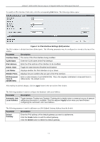
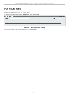
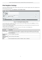
xStack® DGS-3200 Series Layer 2 Gigabit Ethernet Managed Switch Serial Port Settings The user can adjust the Baud Rate and the Auto Logout values. To view the following window, click Configuration > Serial Port Settings: Figure 2- 3. Serial Port Settings window Baud Rate Auto Logout This field specifies the baud rate for the serial port on the Switch. There are four possible baud rates to choose from, 9600, 19200, 38400 and 115200. For a connection to the Switch using the CLI interface, the baud rate must be set to 115200, which is the default setting. Select the logout time used for the console interface. This automatically logs the user out after an idle period of time, as defined. Choose from the following options: 2 mins, 5 mins, 10 mins, 15 mins or Never. The default setting is 10 mins. Click Apply to implement changes made. IP Address The IP ad dress m ay in itially b e set using th e con sole in terface prior t o conn ecting to it th rough th e Eth ernet. If th e Switch I P address ha s not y et bee n c hanged, rea d t he i ntroduction of t he DGS-3200 Series CLI Manual for m ore in formation. The Web manager will display the Switch's current IP settings. To view the following window, click Configuration > IP Address: Figure 2- 4. IP Address window To manually assign the Switch's IP address, subnet mask, and default gateway address: 1. Click the Manual radio button at the top of the window. 2. Enter the appropriate IP Address and Subnet Mask. 3. If accessing the Switch from a different subnet from the one it is installed on, enter the IP address of the default Gateway. If managing the Switch fro m the subnet on which it is i nstalled, the user may leave t he default address (0.0.0.0) in this field. 4. If the Switch has no previously configured VLANs, th e user can u se the Management VLAN Nam e entitled "default". This default Management VLAN contains all of t he Switch ports as m embers. If t he Switch has previously configured VLANs, the user will need t o en ter t he VLAN ID of the VLAN th at contains th e port con nected to th e m anagement station that will access the Switch. The Switch will allow m anagement access from stations with t he same VID listed here. 8
-
 1
1 -
2
-
3
-
4
-
5
-
6
-
7
-
8
-
9
-
10
-
11
-
12
-
13
-
14
-
15
-
 16
16 -
 17
17 -
 18
18 -
 19
19 -
 20
20 -
 21
21 -
 22
22 -
 23
23 -
 24
24 -
 25
25 -
 26
26 -
27
-
28
-
29
-
30
-
31
-
32
-
33
-
34
-
35
-
36
-
37
-
38
-
39
-
40
-
41
-
42
-
43
-
44
-
45
-
46
-
47
-
48
-
49
-
50
-
51
-
52
-
53
-
54
-
55
-
56
-
57
-
58
-
59
-
60
-
61
-
62
-
63
-
64
-
65
-
66
-
67
-
68
-
69
-
70
-
71
-
72
-
73
-
74
-
75
-
76
-
77
-
78
-
79
-
80
-
81
-
82
-
83
-
84
-
85
-
86
-
87
-
88
-
89
-
90
-
91
-
92
-
93
-
94
-
95
-
96
-
97
-
98
-
99
-
100
-
101
-
102
-
103
-
104
-
105
-
106
-
107
-
108
-
109
-
110
-
111
-
112
-
113
-
114
-
115
-
116
-
117
-
118
-
119
-
120
-
121
-
122
-
123
-
124
-
125
-
126
-
127
-
128
-
129
-
130
-
131
-
132
-
133
-
134
-
135
-
136
-
137
-
138
-
139
-
140
-
141
-
142
-
143
-
144
-
145
-
146
-
147
-
148
-
149
-
150
-
151
-
152
-
153
-
154
-
155
-
156
-
157
-
158
-
159
-
160
-
161
-
162
-
163
-
164
-
165
-
166
-
167
-
168
-
169
-
170
-
171
-
172
-
173
-
174
-
175
-
176
-
177
-
178
-
179
-
180
-
181
-
182
-
183
-
184
-
185
-
186
-
187
-
188
-
189
-
190
-
191
-
192
-
193
-
194
-
195
-
196
-
197
-
198
-
199
-
200
-
201
-
202
-
203
-
204
-
205
-
206
-
207
-
208
-
209
-
210
-
211
-
212
-
213
-
214
-
215
-
216
-
217
-
218
-
219
-
220
-
221
-
222
-
223
-
224
-
225
-
226
-
227
-
228
-
229
-
230
-
231
-
232
-
233
-
234
-
235
-
236
-
237
-
238
-
239
-
240
-
241
-
242
-
243
-
244
-
245
-
246
-
247
-
248
-
249
-
250
-
251
-
252
-
253
-
254
-
255
-
256
-
257
-
258
-
259
-
260
-
261
-
262
-
263
-
264
-
265
-
266
-
267
-
268
-
269
-
270
-
271
-
272
-
273
-
274
-
275
-
276
-
277
-
278
-
279
-
280
-
281
-
282
-
283
-
284
-
285
-
286
-
287
-
288
-
289
-
290
-
291
-
292
-
293
-
294
-
295
-
296
-
297
-
298
-
299
-
300
-
301
-
302
 |
 |