D-Link DGS-3200-10 Product Manual - Page 205
Add Access Rule window for IPv4
 |
UPC - 790069306310
View all D-Link DGS-3200-10 manuals
Add to My Manuals
Save this manual to your list of manuals |
Page 205 highlights
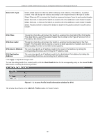
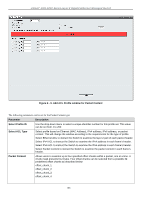
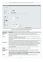
xStack® DGS-3200 Series Layer 2 Gigabit Ethernet Managed Switch Figure 6 - 15. Add Access Rule window for IPv4 To set the Access Rule for IP, adjust the following parameters and click Apply. Parameter Description Access ID (1-200) Action Type in a unique identifier number for this access. This value can be set from 1 to 200. Auto Assign - Ticking this check box will instruct the Switch to automatically assign an Access ID for the rule being created. Select Permit to specify that the packets that match the access rule are forwarded by the Switch, according to any additional rule added (see below). Select Deny to specify that packets that match the access rule are not forwarded by the Switch and will be filtered. Select Mirror to specify that packets that match the access rule are mirrored to a port defined in the config mirror port command. Port Mirroring must be enabled and a target port must be set. Priority (0-7) Replace Priority Replace DSCP (063) VLAN Name Tick the corresponding check box if you want to re-write the 802.1p default priority of a packet to the value entered in the Priority field, which meets the criteria specified previously in this command, before forwarding it on to the specified CoS queue. Otherwise, a packet will have its incoming 802.1p user priority re-written to its original value before being forwarded by the Switch. For more information on priority queues, CoS queues and mapping for 802.1p, see the QoS section of this manual. Tick this check box to replace the Priority value in the adjacent field. Select this option to instruct the Switch to replace the DSCP value (in a packet that meets the selected criteria) with the value entered in the adjacent field. Note: When an ACL rule is added to change both the priority and DSCP of an IPv4 packet, only one of them can be modified due to a chip limitation. Currently the priority is changed when both the priority and DSCP are set to be modified. This field allows the user to enter a VLAN Name in the space provided, which will instruct the Switch to examine the VLAN identifier of each packet header. 192
-
 1
1 -
2
-
3
-
4
-
5
-
6
-
7
-
8
-
9
-
10
-
11
-
12
-
13
-
14
-
15
-
16
-
17
-
18
-
19
-
20
-
21
-
22
-
23
-
24
-
25
-
26
-
27
-
28
-
29
-
30
-
31
-
32
-
33
-
34
-
35
-
36
-
37
-
38
-
39
-
40
-
41
-
42
-
43
-
44
-
45
-
46
-
47
-
48
-
49
-
50
-
51
-
52
-
53
-
54
-
55
-
56
-
57
-
58
-
59
-
60
-
61
-
62
-
63
-
64
-
65
-
66
-
67
-
68
-
69
-
70
-
71
-
72
-
73
-
74
-
75
-
76
-
77
-
78
-
79
-
80
-
81
-
82
-
83
-
84
-
85
-
86
-
87
-
88
-
89
-
90
-
91
-
92
-
93
-
94
-
95
-
96
-
97
-
98
-
99
-
100
-
101
-
102
-
103
-
104
-
105
-
106
-
107
-
108
-
109
-
110
-
111
-
112
-
113
-
114
-
115
-
116
-
117
-
118
-
119
-
120
-
121
-
122
-
123
-
124
-
125
-
126
-
127
-
128
-
129
-
130
-
131
-
132
-
133
-
134
-
135
-
136
-
137
-
138
-
139
-
140
-
141
-
142
-
143
-
144
-
145
-
146
-
147
-
148
-
149
-
150
-
151
-
152
-
153
-
154
-
155
-
156
-
157
-
158
-
159
-
160
-
161
-
162
-
163
-
164
-
165
-
166
-
167
-
168
-
169
-
170
-
171
-
172
-
173
-
174
-
175
-
176
-
177
-
178
-
179
-
180
-
181
-
182
-
183
-
184
-
185
-
186
-
187
-
188
-
189
-
190
-
191
-
192
-
193
-
194
-
195
-
196
-
197
-
198
-
199
-
 200
200 -
 201
201 -
 202
202 -
 203
203 -
 204
204 -
 205
205 -
 206
206 -
 207
207 -
 208
208 -
 209
209 -
 210
210 -
211
-
212
-
213
-
214
-
215
-
216
-
217
-
218
-
219
-
220
-
221
-
222
-
223
-
224
-
225
-
226
-
227
-
228
-
229
-
230
-
231
-
232
-
233
-
234
-
235
-
236
-
237
-
238
-
239
-
240
-
241
-
242
-
243
-
244
-
245
-
246
-
247
-
248
-
249
-
250
-
251
-
252
-
253
-
254
-
255
-
256
-
257
-
258
-
259
-
260
-
261
-
262
-
263
-
264
-
265
-
266
-
267
-
268
-
269
-
270
-
271
-
272
-
273
-
274
-
275
-
276
-
277
-
278
-
279
-
280
-
281
-
282
-
283
-
284
-
285
-
286
-
287
-
288
-
289
-
290
-
291
-
292
-
293
-
294
-
295
-
296
-
297
-
298
-
299
-
300
-
301
-
302
 |
 |
