Yamaha AW4416 Owner's Manual - Page 36
Signal flow within the AW4416 - digital mixer and recorder
 |
View all Yamaha AW4416 manuals
Add to My Manuals
Save this manual to your list of manuals |
Page 36 highlights
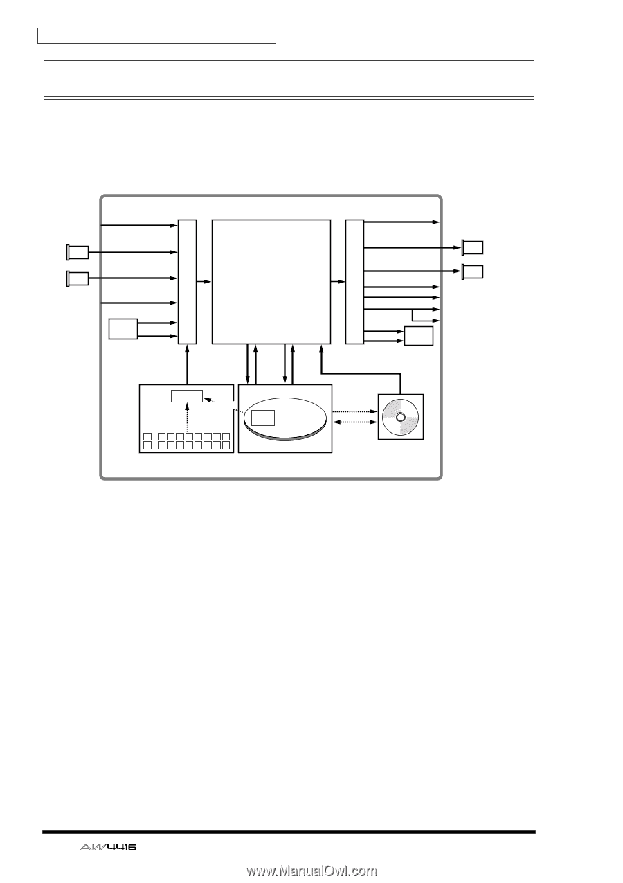
Chapter1-Welcome to the world of the AW4416 Signal flow within the AW4416 The following diagram shows the general signal flow of the AW4416. As you can see from this diagram, the AW4416 consists of several sections: input patch, output patch, mixer, sampling pads, recorder, and CD-RW drive (optional). INPUT jacks 1-8 I/O card I/O card ×8 OPTION I/O slot 1 ×8 OPTION I/O slot 2 ×8 DIGITAL STEREO ×2 IN connector ×2 Effect 1/2 ×2 Mixer section Input channels 1-24 Effect returns 1/2 Monitor channels 1-16 Buses 1-8 STEREO bus AUX buses 1-8 SOLO bus Channel insert I/O Stereo bus insert I/O ×8 ×16 ×16 ×2 ×2 Output patch Input patch ×4 OMNI OUT jacks 1-4 OPTION I/O ×8 slot 1 I/O OPTION I/O card ×8 slot 2 I/O card ×2 ×2 STEREO OUT jacks DIGITAL STEREO OUT jack ×2 MONITOR OUT jacks PHONES jack Effect 1/2 ×2 D-RAM Import Trigger Audio File A 12345678 B 12345678 Sampling pads section Recorder section CD Writing Data Backup/ Restore CD-RW Drive AW4416 The signal flow within each section is explained in detail in the pages that follow. 22 - Operation Guide
-
 1
1 -
2
-
3
-
4
-
5
-
6
-
7
-
8
-
9
-
10
-
11
-
12
-
13
-
14
-
15
-
16
-
17
-
18
-
19
-
20
-
21
-
22
-
23
-
24
-
25
-
26
-
27
-
28
-
29
-
30
-
 31
31 -
 32
32 -
 33
33 -
 34
34 -
 35
35 -
 36
36 -
 37
37 -
 38
38 -
 39
39 -
 40
40 -
 41
41 -
42
-
43
-
44
-
45
-
46
-
47
-
48
-
49
-
50
-
51
-
52
-
53
-
54
-
55
-
56
-
57
-
58
-
59
-
60
-
61
-
62
-
63
-
64
-
65
-
66
-
67
-
68
-
69
-
70
-
71
-
72
-
73
-
74
-
75
-
76
-
77
-
78
-
79
-
80
-
81
-
82
-
83
-
84
-
85
-
86
-
87
-
88
-
89
-
90
-
91
-
92
-
93
-
94
-
95
-
96
-
97
-
98
-
99
-
100
-
101
-
102
-
103
-
104
-
105
-
106
-
107
-
108
-
109
-
110
-
111
-
112
-
113
-
114
-
115
-
116
-
117
-
118
-
119
-
120
-
121
-
122
-
123
-
124
-
125
-
126
-
127
-
128
-
129
-
130
-
131
-
132
-
133
-
134
-
135
-
136
-
137
-
138
-
139
-
140
-
141
-
142
-
143
-
144
-
145
-
146
-
147
-
148
-
149
-
150
-
151
-
152
-
153
-
154
-
155
-
156
-
157
-
158
-
159
-
160
-
161
-
162
-
163
-
164
-
165
-
166
-
167
-
168
-
169
-
170
-
171
-
172
-
173
-
174
-
175
-
176
-
177
-
178
-
179
-
180
-
181
-
182
-
183
-
184
-
185
-
186
-
187
-
188
-
189
-
190
-
191
-
192
-
193
-
194
-
195
-
196
-
197
-
198
-
199
-
200
-
201
-
202
-
203
-
204
-
205
-
206
-
207
-
208
-
209
-
210
-
211
-
212
-
213
-
214
-
215
-
216
-
217
-
218
-
219
-
220
-
221
-
222
-
223
-
224
-
225
-
226
-
227
-
228
-
229
-
230
-
231
-
232
-
233
-
234
-
235
-
236
-
237
-
238
-
239
-
240
-
241
-
242
-
243
-
244
-
245
-
246
-
247
-
248
-
249
-
250
-
251
-
252
-
253
-
254
-
255
-
256
-
257
-
258
-
259
-
260
-
261
-
262
-
263
-
264
-
265
-
266
-
267
-
268
-
269
-
270
-
271
-
272
-
273
-
274
-
275
-
276
-
277
-
278
-
279
 |
 |