Yamaha AW4416 Owner's Manual - Page 42
Buses 1–8, AUX buses 1–8 - mastering
 |
View all Yamaha AW4416 manuals
Add to My Manuals
Save this manual to your list of manuals |
Page 42 highlights
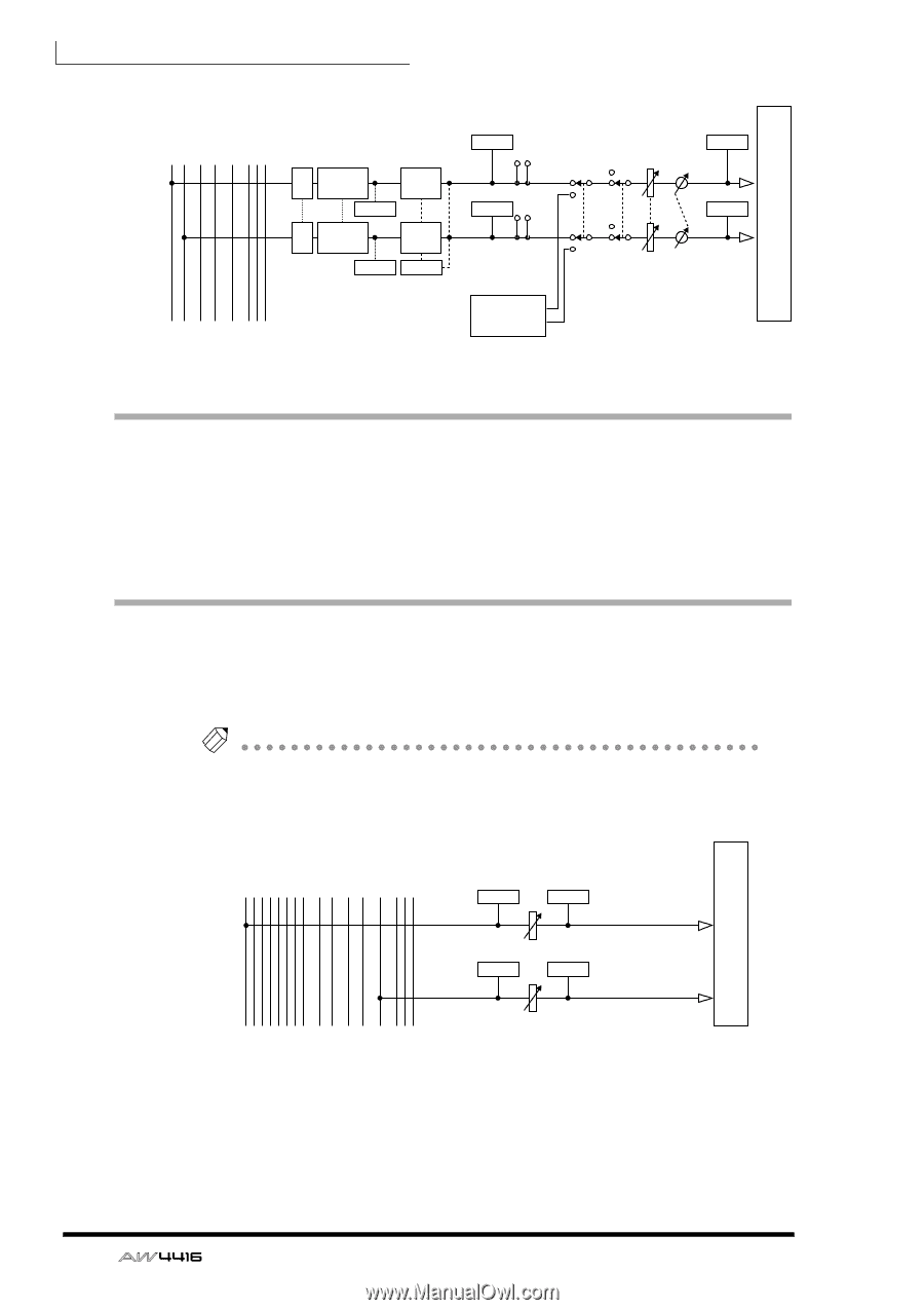
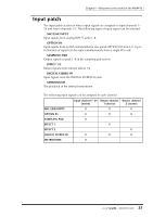
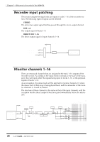
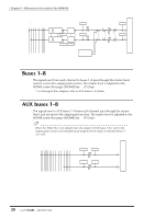
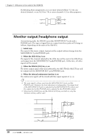
STEREO L STEREO R SOLO L SOLO R AUX 1 AUX 6 AUX 7(EFF1) AUX 8(EFF2) OUTPUT PATCH Chapter1-Welcome to the world of the AW4416 ... METER INSERT ATT 4BAND EQ DYNAMICS METER (EQ) ATT 4BAND EQ DYNAMICS METER STEREO METER ON LEVEL BAL METER METER METER (EQ) (Gain Reduction) CD PLAY mode CD-RW L DRIVE R Buses 1-8 The signals sent from each channel to buses 1-8 pass through the master level, and are sent to the output patch section. The master level is adjusted in the HOME screen Bus page ([HOME] key ¡ [F3] key). * For the signal flow diagram, refer to AUX buses 1-8, below. AUX buses 1-8 The signals sent to AUX buses 1-8 from each channel pass through the master level, and are sent to the output patch section. The master level is adjusted in the HOME screen Bus page ([HOME] key ¡ [F3] key). Tip! When the AW4416 is in its default state, the output of AUX buses 7/8 is sent to the output patch section, and simultaneously assigned to the inputs of internal effects 1/ 2 as well. BUS1 BUS2 BUS3 BUS4 BUS5 BUS6 BUS7 BUS8 STEREO L STEREO R SOLO L SOLO R AUX 1 AUX 6 AUX 7(EFF1) AUX 8(EFF2) OUTPUT PATCH ... METER METER BUS1(...8) LEVEL METER METER LEVEL AUX1(...8) 28 - Operation Guide
-
 1
1 -
2
-
3
-
4
-
5
-
6
-
7
-
8
-
9
-
10
-
11
-
12
-
13
-
14
-
15
-
16
-
17
-
18
-
19
-
20
-
21
-
22
-
23
-
24
-
25
-
26
-
27
-
28
-
29
-
30
-
31
-
32
-
33
-
34
-
35
-
36
-
 37
37 -
 38
38 -
 39
39 -
 40
40 -
 41
41 -
 42
42 -
 43
43 -
 44
44 -
 45
45 -
 46
46 -
 47
47 -
48
-
49
-
50
-
51
-
52
-
53
-
54
-
55
-
56
-
57
-
58
-
59
-
60
-
61
-
62
-
63
-
64
-
65
-
66
-
67
-
68
-
69
-
70
-
71
-
72
-
73
-
74
-
75
-
76
-
77
-
78
-
79
-
80
-
81
-
82
-
83
-
84
-
85
-
86
-
87
-
88
-
89
-
90
-
91
-
92
-
93
-
94
-
95
-
96
-
97
-
98
-
99
-
100
-
101
-
102
-
103
-
104
-
105
-
106
-
107
-
108
-
109
-
110
-
111
-
112
-
113
-
114
-
115
-
116
-
117
-
118
-
119
-
120
-
121
-
122
-
123
-
124
-
125
-
126
-
127
-
128
-
129
-
130
-
131
-
132
-
133
-
134
-
135
-
136
-
137
-
138
-
139
-
140
-
141
-
142
-
143
-
144
-
145
-
146
-
147
-
148
-
149
-
150
-
151
-
152
-
153
-
154
-
155
-
156
-
157
-
158
-
159
-
160
-
161
-
162
-
163
-
164
-
165
-
166
-
167
-
168
-
169
-
170
-
171
-
172
-
173
-
174
-
175
-
176
-
177
-
178
-
179
-
180
-
181
-
182
-
183
-
184
-
185
-
186
-
187
-
188
-
189
-
190
-
191
-
192
-
193
-
194
-
195
-
196
-
197
-
198
-
199
-
200
-
201
-
202
-
203
-
204
-
205
-
206
-
207
-
208
-
209
-
210
-
211
-
212
-
213
-
214
-
215
-
216
-
217
-
218
-
219
-
220
-
221
-
222
-
223
-
224
-
225
-
226
-
227
-
228
-
229
-
230
-
231
-
232
-
233
-
234
-
235
-
236
-
237
-
238
-
239
-
240
-
241
-
242
-
243
-
244
-
245
-
246
-
247
-
248
-
249
-
250
-
251
-
252
-
253
-
254
-
255
-
256
-
257
-
258
-
259
-
260
-
261
-
262
-
263
-
264
-
265
-
266
-
267
-
268
-
269
-
270
-
271
-
272
-
273
-
274
-
275
-
276
-
277
-
278
-
279
 |
 |