Yamaha AW4416 Owner's Manual - Page 45
Parts and their functions, Top panel, Analog input/output - workstation
 |
View all Yamaha AW4416 manuals
Add to My Manuals
Save this manual to your list of manuals |
Page 45 highlights
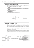
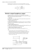
2 Parts and their functions This chapter explains the names and functions of the various objects on the top panel, rear panel, and front panel. Note Names of the controllers on the top panel are enclosed in square brackets [ ], in order to distinguish them from the "software" knobs or buttons displayed in the display. Example: [SEL] key, EQ [Q] control Top panel Analog input/output section 2 34 1 PEAK 2 PEAK 3 PEAK 4 PEAK 5 PEAK 6 PEAK 7 PEAK 8 PEAK PHONES MONITOR OUT LINE MIC LINE MIC LINE MIC LINE MIC LINE MIC LINE MIC LINE MIC LINE MIC MIN MAX MIN MAX 1 1 PEAK 2 PEAK 3 PEAK 4 PEAK 5 PEAK 6 PEAK 7 PEAK 8 PEAK PHONES MONITOR OUT LINE MIC LINE MIC LINE MIC LINE MIC LINE MIC LINE MIC LINE MIC LINE MIC MIN MAX MIN MAX PROFESSIONAL AUDIO WORKSTATION 1 [GAIN] controls These controls adjust the input sensitivity of INPUT jacks 1-8. The supported input level range is -46 dB- +4 dB. B PEAK indicators These LEDs will light red when the input signal of INPUT jacks 1-8 reaches a level 3 dB below the clipping point. C [PHONES] control This control adjusts the output level of the signal that is sent from the rear panel PHONES jack. 31 - Operation Guide
-
 1
1 -
2
-
3
-
4
-
5
-
6
-
7
-
8
-
9
-
10
-
11
-
12
-
13
-
14
-
15
-
16
-
17
-
18
-
19
-
20
-
21
-
22
-
23
-
24
-
25
-
26
-
27
-
28
-
29
-
30
-
31
-
32
-
33
-
34
-
35
-
36
-
37
-
38
-
39
-
 40
40 -
 41
41 -
 42
42 -
 43
43 -
 44
44 -
 45
45 -
 46
46 -
 47
47 -
 48
48 -
 49
49 -
 50
50 -
51
-
52
-
53
-
54
-
55
-
56
-
57
-
58
-
59
-
60
-
61
-
62
-
63
-
64
-
65
-
66
-
67
-
68
-
69
-
70
-
71
-
72
-
73
-
74
-
75
-
76
-
77
-
78
-
79
-
80
-
81
-
82
-
83
-
84
-
85
-
86
-
87
-
88
-
89
-
90
-
91
-
92
-
93
-
94
-
95
-
96
-
97
-
98
-
99
-
100
-
101
-
102
-
103
-
104
-
105
-
106
-
107
-
108
-
109
-
110
-
111
-
112
-
113
-
114
-
115
-
116
-
117
-
118
-
119
-
120
-
121
-
122
-
123
-
124
-
125
-
126
-
127
-
128
-
129
-
130
-
131
-
132
-
133
-
134
-
135
-
136
-
137
-
138
-
139
-
140
-
141
-
142
-
143
-
144
-
145
-
146
-
147
-
148
-
149
-
150
-
151
-
152
-
153
-
154
-
155
-
156
-
157
-
158
-
159
-
160
-
161
-
162
-
163
-
164
-
165
-
166
-
167
-
168
-
169
-
170
-
171
-
172
-
173
-
174
-
175
-
176
-
177
-
178
-
179
-
180
-
181
-
182
-
183
-
184
-
185
-
186
-
187
-
188
-
189
-
190
-
191
-
192
-
193
-
194
-
195
-
196
-
197
-
198
-
199
-
200
-
201
-
202
-
203
-
204
-
205
-
206
-
207
-
208
-
209
-
210
-
211
-
212
-
213
-
214
-
215
-
216
-
217
-
218
-
219
-
220
-
221
-
222
-
223
-
224
-
225
-
226
-
227
-
228
-
229
-
230
-
231
-
232
-
233
-
234
-
235
-
236
-
237
-
238
-
239
-
240
-
241
-
242
-
243
-
244
-
245
-
246
-
247
-
248
-
249
-
250
-
251
-
252
-
253
-
254
-
255
-
256
-
257
-
258
-
259
-
260
-
261
-
262
-
263
-
264
-
265
-
266
-
267
-
268
-
269
-
270
-
271
-
272
-
273
-
274
-
275
-
276
-
277
-
278
-
279
 |
 |
