Yamaha AW4416 Owner's Manual - Page 92
Input channels 1-16, Input channels 17-24 + return channels, Monitor channels, Mixer Input
 |
View all Yamaha AW4416 manuals
Add to My Manuals
Save this manual to your list of manuals |
Page 92 highlights
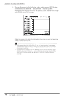
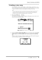
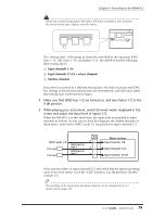
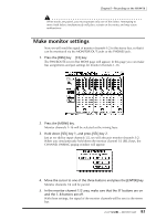
Chapter5-Recording on the AW4416 When you switch mixing layers, the faders will move instantly to new positions. Be careful not to place objects near the faders. MIXING LAYER 1-16 INPUT 17-24 RTN INPUT MONI RECORDER MIXING LAYER 1-16 INPUT 17-24 RTN INPUT MONI RECORDER PROFESSIONAL AUDIO WORKSTATION The "mixing layer" is the group of channels controlled by the top panel [ON] keys 1-16, [SEL] keys 1-16, and faders 1-16. The AW4416 has the following three mixing layers: 1 Input channels 1-16 B Input channels 17-24 + return channels C Monitor channels Even when you switch to a different mixing layer, the fader locations and [ON] key settings of the previous mixing layer are remembered, and will return when that mixing layer is selected once again. 4. Make sure that [ON] keys 1/2 are turned on, and raise faders 1/2 to the 0 dB position. 5. While playing your instrument, watch the level meters displayed in the screen and adjust the input level of inputs 1/2. When the AW4416 is in the initial state, the input jacks are patched to input channels as follows. As you can see from this diagram, the rhythm machine (or drum mics) connected to INPUT jacks 1/2 are patched to input channels 1/2. INPUT jacks 1-8 I/O card I/O card OPTION I/O slot 1 OPTION I/O slot 2 Input patch ×8 ×8 ×8 Mixer section Input channels 1-8 Input channels 9-16 Input channels 17-24 Now raise the faders of input channels 1/2 and check that the signals are being input. If the level meters reach the "CLIP" position, you should lower [GAIN] controls 1/2. Tip! The patching of the input jacks and input channels can be changed freely. For details refer to page 133. 79 - Operation Guide
-
 1
1 -
2
-
3
-
4
-
5
-
6
-
7
-
8
-
9
-
10
-
11
-
12
-
13
-
14
-
15
-
16
-
17
-
18
-
19
-
20
-
21
-
22
-
23
-
24
-
25
-
26
-
27
-
28
-
29
-
30
-
31
-
32
-
33
-
34
-
35
-
36
-
37
-
38
-
39
-
40
-
41
-
42
-
43
-
44
-
45
-
46
-
47
-
48
-
49
-
50
-
51
-
52
-
53
-
54
-
55
-
56
-
57
-
58
-
59
-
60
-
61
-
62
-
63
-
64
-
65
-
66
-
67
-
68
-
69
-
70
-
71
-
72
-
73
-
74
-
75
-
76
-
77
-
78
-
79
-
80
-
81
-
82
-
83
-
84
-
85
-
86
-
 87
87 -
 88
88 -
 89
89 -
 90
90 -
 91
91 -
 92
92 -
 93
93 -
 94
94 -
 95
95 -
 96
96 -
 97
97 -
98
-
99
-
100
-
101
-
102
-
103
-
104
-
105
-
106
-
107
-
108
-
109
-
110
-
111
-
112
-
113
-
114
-
115
-
116
-
117
-
118
-
119
-
120
-
121
-
122
-
123
-
124
-
125
-
126
-
127
-
128
-
129
-
130
-
131
-
132
-
133
-
134
-
135
-
136
-
137
-
138
-
139
-
140
-
141
-
142
-
143
-
144
-
145
-
146
-
147
-
148
-
149
-
150
-
151
-
152
-
153
-
154
-
155
-
156
-
157
-
158
-
159
-
160
-
161
-
162
-
163
-
164
-
165
-
166
-
167
-
168
-
169
-
170
-
171
-
172
-
173
-
174
-
175
-
176
-
177
-
178
-
179
-
180
-
181
-
182
-
183
-
184
-
185
-
186
-
187
-
188
-
189
-
190
-
191
-
192
-
193
-
194
-
195
-
196
-
197
-
198
-
199
-
200
-
201
-
202
-
203
-
204
-
205
-
206
-
207
-
208
-
209
-
210
-
211
-
212
-
213
-
214
-
215
-
216
-
217
-
218
-
219
-
220
-
221
-
222
-
223
-
224
-
225
-
226
-
227
-
228
-
229
-
230
-
231
-
232
-
233
-
234
-
235
-
236
-
237
-
238
-
239
-
240
-
241
-
242
-
243
-
244
-
245
-
246
-
247
-
248
-
249
-
250
-
251
-
252
-
253
-
254
-
255
-
256
-
257
-
258
-
259
-
260
-
261
-
262
-
263
-
264
-
265
-
266
-
267
-
268
-
269
-
270
-
271
-
272
-
273
-
274
-
275
-
276
-
277
-
278
-
279
 |
 |
