Brother International PE-DESIGN Ver.5 Users Manual - English - Page 30
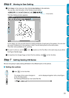
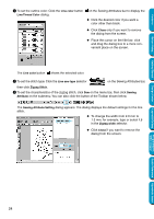
Step 5 Converting to Handle Image
 |
View all Brother International PE-DESIGN Ver.5 manuals
Add to My Manuals
Save this manual to your list of manuals |
Page 30 highlights
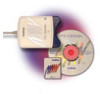
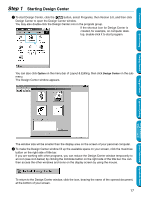
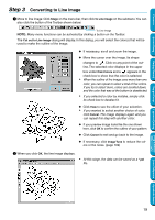
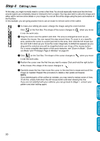
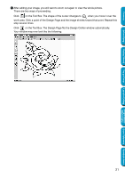
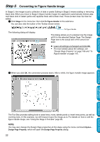
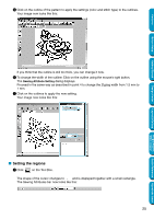
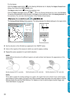
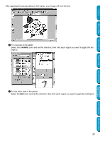
Contents Before Using Getting Started Step 5 Converting to Figure Handle Image In Stage 2, the image is just a collection of dots or pixels. Editing in Stage 2 means adding or removing black dots. When you move to Stage 3 (figure handle image) the application automatically follows adjacent black dots to detect paths and replaces them with broken lines. Those broken lines can then be edited. 1 Click Stage on the menu bar, then click To Figure Handle on the submenu. You can also click the button of the Toolbar shown below: The following dialog will display. To Figure Handle This dialog allows you to preview how the image will fit in the selected Design Page. The Design Page size is the actual size of the area to be sewn. N Leave all settings unchanged and click OK. • For more details about the settings, see "Design Page Property" on page 106 and "To Figure Handle" on page 110. 2 When you click OK, the conversion process starts. After a while, the figure handle image appears. Design Center Layout & Editing Programmable Stitch Creator Quick Reference Alphabetic Index The Tool Box provides editing tools to draw lines, move, delete points or insert new points, as well as zooming tools. In this example, we will however leave the image as is. For details on how to edit the figure handle image, see "Using the Stage 3 Tool Box" page 65. NOTE: You may also change the Design Page properties at this stage using the menu command Option Design Page Property, which will open the Design Page Property dialog. 22
-
 1
1 -
2
-
3
-
4
-
5
-
6
-
7
-
8
-
9
-
10
-
11
-
12
-
13
-
14
-
15
-
16
-
17
-
18
-
19
-
20
-
21
-
22
-
23
-
24
-
 25
25 -
 26
26 -
 27
27 -
 28
28 -
 29
29 -
 30
30 -
 31
31 -
 32
32 -
 33
33 -
 34
34 -
 35
35 -
36
-
37
-
38
-
39
-
40
-
41
-
42
-
43
-
44
-
45
-
46
-
47
-
48
-
49
-
50
-
51
-
52
-
53
-
54
-
55
-
56
-
57
-
58
-
59
-
60
-
61
-
62
-
63
-
64
-
65
-
66
-
67
-
68
-
69
-
70
-
71
-
72
-
73
-
74
-
75
-
76
-
77
-
78
-
79
-
80
-
81
-
82
-
83
-
84
-
85
-
86
-
87
-
88
-
89
-
90
-
91
-
92
-
93
-
94
-
95
-
96
-
97
-
98
-
99
-
100
-
101
-
102
-
103
-
104
-
105
-
106
-
107
-
108
-
109
-
110
-
111
-
112
-
113
-
114
-
115
-
116
-
117
-
118
-
119
-
120
-
121
-
122
-
123
-
124
-
125
-
126
-
127
-
128
-
129
-
130
-
131
-
132
-
133
-
134
-
135
-
136
-
137
-
138
-
139
-
140
-
141
-
142
-
143
-
144
-
145
-
146
-
147
-
148
-
149
-
150
-
151
-
152
-
153
-
154
-
155
-
156
-
157
-
158
-
159
-
160
-
161
-
162
-
163
-
164
-
165
-
166
-
167
-
168
-
169
-
170
-
171
-
172
-
173
-
174
-
175
-
176
-
177
-
178
-
179
-
180
-
181
-
182
-
183
-
184
-
185
-
186
-
187
-
188
-
189
-
190
-
191
-
192
-
193
-
194
-
195
-
196
-
197
-
198
-
199
-
200
-
201
-
202
-
203
-
204
-
205
-
206
-
207
-
208
-
209
-
210
-
211
-
212
-
213
-
214
-
215
-
216
-
217
-
218
-
219
-
220
-
221
-
222
-
223
-
224
-
225
-
226
-
227
-
228
-
229
-
230
-
231
-
232
-
233
-
234
-
235
-
236
-
237
-
238
-
239
-
240
-
241
-
242
-
243
-
244
-
245
-
246
-
247
-
248
-
249
-
250
-
251
-
252
-
253
-
254
-
255
-
256
-
257
-
258
-
259
-
260
-
261
-
262
-
263
-
264
-
265
-
266
-
267
-
268
-
269
-
270
-
271
-
272
-
273
-
274
 |
 |