D-Link DES-3528 Product Manual - Page 125
Multicast VLAN, Browse MLD Snooping Counter window, Clear Counter, Refresh, <<Back
 |
UPC - 790069314346
View all D-Link DES-3528 manuals
Add to My Manuals
Save this manual to your list of manuals |
Page 125 highlights
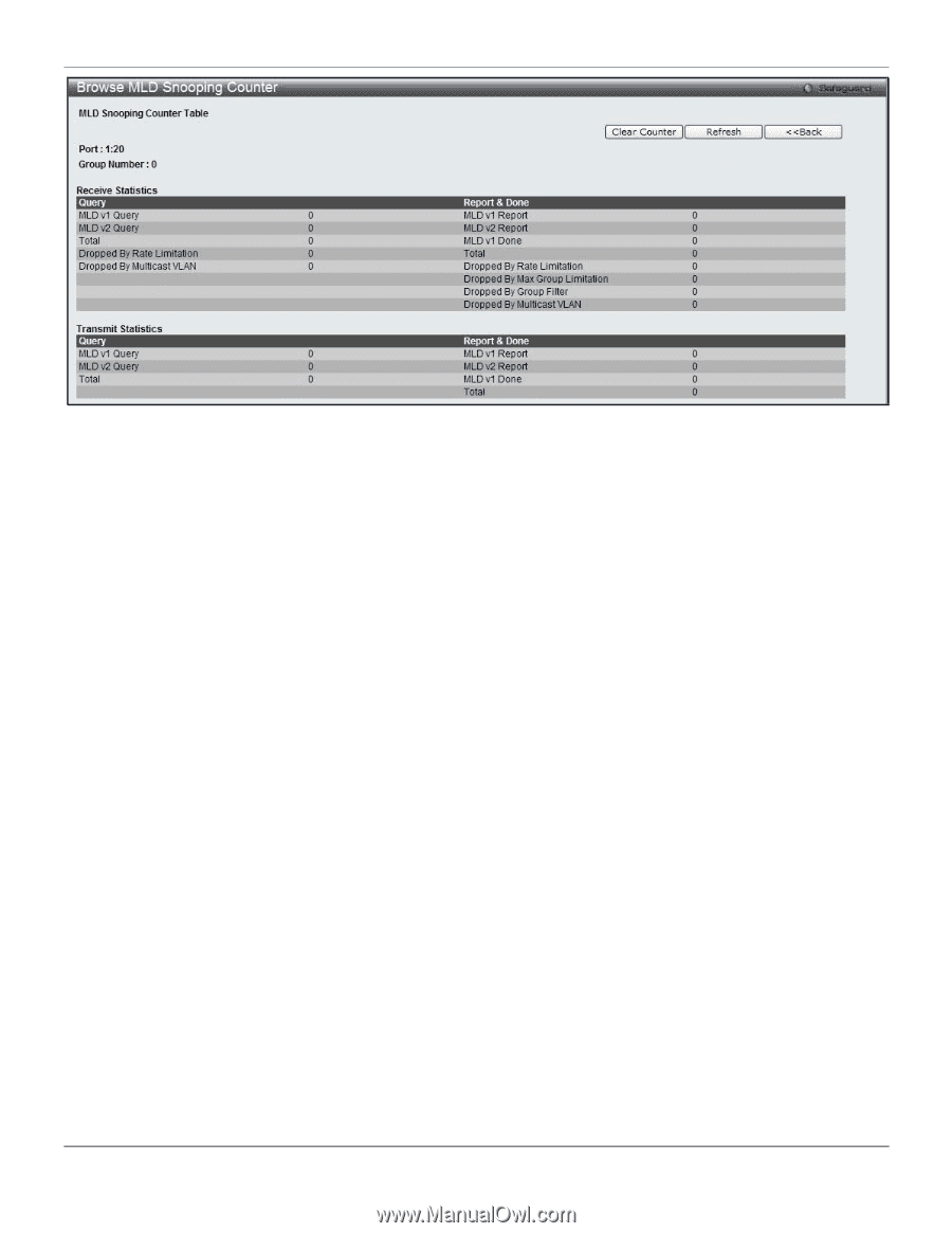
xStack® DES-3528/DES-3552 Series Layer 2 Stackable Fast Ethernet Managed Switch Web UI Reference Guide Figure 4-64 Browse MLD Snooping Counter window Click the Clear Counter button to clear all the information displayed in the fields. Click the Refresh button to refresh the display table so that new information will appear. Click the
-
 1
1 -
2
-
3
-
4
-
5
-
6
-
7
-
8
-
9
-
10
-
11
-
12
-
13
-
14
-
15
-
16
-
17
-
18
-
19
-
20
-
21
-
22
-
23
-
24
-
25
-
26
-
27
-
28
-
29
-
30
-
31
-
32
-
33
-
34
-
35
-
36
-
37
-
38
-
39
-
40
-
41
-
42
-
43
-
44
-
45
-
46
-
47
-
48
-
49
-
50
-
51
-
52
-
53
-
54
-
55
-
56
-
57
-
58
-
59
-
60
-
61
-
62
-
63
-
64
-
65
-
66
-
67
-
68
-
69
-
70
-
71
-
72
-
73
-
74
-
75
-
76
-
77
-
78
-
79
-
80
-
81
-
82
-
83
-
84
-
85
-
86
-
87
-
88
-
89
-
90
-
91
-
92
-
93
-
94
-
95
-
96
-
97
-
98
-
99
-
100
-
101
-
102
-
103
-
104
-
105
-
106
-
107
-
108
-
109
-
110
-
111
-
112
-
113
-
114
-
115
-
116
-
117
-
118
-
119
-
 120
120 -
 121
121 -
 122
122 -
 123
123 -
 124
124 -
 125
125 -
 126
126 -
 127
127 -
 128
128 -
 129
129 -
 130
130 -
131
-
132
-
133
-
134
-
135
-
136
-
137
-
138
-
139
-
140
-
141
-
142
-
143
-
144
-
145
-
146
-
147
-
148
-
149
-
150
-
151
-
152
-
153
-
154
-
155
-
156
-
157
-
158
-
159
-
160
-
161
-
162
-
163
-
164
-
165
-
166
-
167
-
168
-
169
-
170
-
171
-
172
-
173
-
174
-
175
-
176
-
177
-
178
-
179
-
180
-
181
-
182
-
183
-
184
-
185
-
186
-
187
-
188
-
189
-
190
-
191
-
192
-
193
-
194
-
195
-
196
-
197
-
198
-
199
-
200
-
201
-
202
-
203
-
204
-
205
-
206
-
207
-
208
-
209
-
210
-
211
-
212
-
213
-
214
-
215
-
216
-
217
-
218
-
219
-
220
-
221
-
222
-
223
-
224
-
225
-
226
-
227
-
228
-
229
-
230
-
231
-
232
-
233
-
234
-
235
-
236
-
237
-
238
-
239
-
240
-
241
-
242
-
243
-
244
-
245
-
246
-
247
-
248
-
249
-
250
-
251
-
252
-
253
-
254
-
255
-
256
-
257
-
258
-
259
-
260
-
261
-
262
-
263
-
264
-
265
-
266
-
267
-
268
-
269
-
270
-
271
-
272
-
273
-
274
-
275
-
276
-
277
-
278
-
279
-
280
-
281
-
282
-
283
-
284
-
285
-
286
-
287
-
288
-
289
-
290
-
291
-
292
-
293
-
294
-
295
-
296
-
297
-
298
-
299
-
300
-
301
-
302
-
303
-
304
-
305
-
306
-
307
-
308
-
309
-
310
-
311
-
312
-
313
-
314
-
315
-
316
-
317
-
318
-
319
-
320
-
321
-
322
-
323
-
324
-
325
-
326
-
327
-
328
-
329
-
330
-
331
-
332
-
333
-
334
-
335
-
336
-
337
-
338
-
339
-
340
-
341
-
342
-
343
-
344
-
345
-
346
-
347
-
348
-
349
-
350
-
351
-
352
-
353
-
354
-
355
-
356
-
357
-
358
-
359
-
360
-
361
-
362
-
363
-
364
-
365
-
366
-
367
 |
 |
xStack® DES-3528/DES-3552 Series Layer 2 Stackable Fast Ethernet Managed Switch Web UI Reference Guide
Figure 4-64 Browse MLD Snooping Counter window
Click the
Clear Counter
button to clear all the information displayed in the fields.
Click the
Refresh
button to refresh the display table so that new information will appear.
Click the
<<Back
button to return to the previous page.
Multicast VLAN
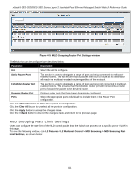
In a switching environment, multiple VLANs may exist. Every time when a multicast query passes through the Switch,
the Switch must forward separate different copies of the data to each VLAN on the system, which, in turn, increases
data traffic and may clog up the traffic path. To lighten the traffic load, multicast VLANs may be incorporated. These
multicast VLANs will allow the Switch to forward this multicast traffic as one copy to recipients of the multicast VLAN,
instead of multiple copies.
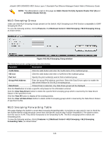
Regardless of other normal VLANs that are incorporated on the Switch, users may add any ports to the multicast VLAN
where they wish multicast traffic to be sent. Users are to set up a source port, where the multicast traffic is entering the
Switch, and then set the ports where the incoming multicast traffic is to be sent. The source port cannot be a recipient
port and if configured to do so, will cause error messages to be produced by the Switch. Once properly configured, the
stream of multicast data will be relayed to the receiver ports in a much more timely and reliable fashion.
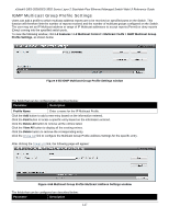
Restrictions and Provisos:
The Multicast VLAN feature of this Switch does have some restrictions and limitations, such as:
1.
Multicast VLANs can be implemented on edge and non-edge switches.
2.
Member ports and source ports can be used in multiple ISM VLANs. But member ports and source ports
cannot be the same port in a specific ISM VLAN.
3.
The Multicast VLAN is exclusive with normal 802.1q VLANs, which means that VLAN IDs (VIDs) and VLAN
Names of 802.1q VLANs and ISM VLANs cannot be the same. Once a VID or VLAN Name is chosen for any
VLAN, it cannot be used for any other VLAN.
4.
The normal display of configured VLANs will not display configured Multicast VLANs.
5.
Once an ISM VLAN is enabled, the corresponding IGMP snooping state of this VLAN will also be enabled.
Users cannot disable the IGMP feature for an enabled ISM VLAN.
6.
One IP multicast address cannot be added to multiple ISM VLANs, yet multiple Ranges can be added to one
ISM VLAN.
116