D-Link DES-3528 Product Manual - Page 161
Traffic Control Settings, System Configuration > Port Configuration > Port Settings
 |
UPC - 790069314346
View all D-Link DES-3528 manuals
Add to My Manuals
Save this manual to your list of manuals |
Page 161 highlights
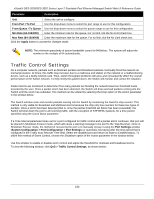
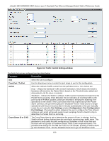
xStack® DES-3528/DES-3552 Series Layer 2 Stackable Fast Ethernet Managed Switch Web UI Reference Guide Parameter Description Unit Select the unit to configure. From Port / To Port Use the drop-down menu to select the port range to use for this configuration. From Queue / To Queue Use the drop-down menu to select the queue range to use for this configuration. Min Rate (64-1024000) Enter the minimum rate for the queue. For no limit, tick the No Limit check box. Max Rate (64-1024000) Enter the maximum rate for the queue. For no limit, tick the No Limit check box. Click the Apply button to accept the changes made. NOTE: The minimum granularity of queue bandwidth control is 64Kbit/sec. The system will adjust the number to the multiple of 64 automatically. Traffic Control Settings On a computer network, packets such as Multicast packets and Broadcast packets continually flood the network as normal procedure. At times, this traffic may increase due to a malicious end station on the network or a malfunctioning device, such as a faulty network card. Thus, switch throughput problems will arise and consequently affect the overall performance of the Switch network. To help rectify this packet storm, the Switch will monitor and control the situation. Packet storms are monitored to determine if too many packets are flooding the network based on threshold levels provided by the user. Once a packet storm has been detected, the Switch will drop overload packets coming into the Switch until the storm has subsided. This method can be utilized by selecting the Drop option of the Action parameter in the window below. The Switch will also scan and monitor packets coming into the Switch by monitoring the Switch's chip counter. This method is only viable for Broadcast and Multicast storms because the chip only has counters for these two types of packets. Once a storm has been detected (that is, once the packet threshold set below has been exceeded), the Switch will shut down the port to all incoming traffic, with the exception of STP BPDU packets, for a time period specified using the Count Down parameter. If a Time Interval parameter times-out for a port configured for traffic control and a packet storm continues, that port will be placed in Shutdown Forever mode, which will cause a warning message to be sent to the Trap Receiver. Once in Shutdown Forever mode, the method of recovering the port is to manually recoup it using the Port Settings window (System Configuration > Port Configuration > Port Settings) or automatic recovering after the time period that is configured in the Traffic Auto Recover Time field. Select the disabled port and return its State to Enabled status. To utilize this method of Storm Control, choose the Shutdown option of the Action parameter in the window below. Use this window to enable or disable storm control and adjust the threshold for multicast and broadcast storms. To view the following window, click QoS > Traffic Control Settings, as shown below: 152
-
 1
1 -
2
-
3
-
4
-
5
-
6
-
7
-
8
-
9
-
10
-
11
-
12
-
13
-
14
-
15
-
16
-
17
-
18
-
19
-
20
-
21
-
22
-
23
-
24
-
25
-
26
-
27
-
28
-
29
-
30
-
31
-
32
-
33
-
34
-
35
-
36
-
37
-
38
-
39
-
40
-
41
-
42
-
43
-
44
-
45
-
46
-
47
-
48
-
49
-
50
-
51
-
52
-
53
-
54
-
55
-
56
-
57
-
58
-
59
-
60
-
61
-
62
-
63
-
64
-
65
-
66
-
67
-
68
-
69
-
70
-
71
-
72
-
73
-
74
-
75
-
76
-
77
-
78
-
79
-
80
-
81
-
82
-
83
-
84
-
85
-
86
-
87
-
88
-
89
-
90
-
91
-
92
-
93
-
94
-
95
-
96
-
97
-
98
-
99
-
100
-
101
-
102
-
103
-
104
-
105
-
106
-
107
-
108
-
109
-
110
-
111
-
112
-
113
-
114
-
115
-
116
-
117
-
118
-
119
-
120
-
121
-
122
-
123
-
124
-
125
-
126
-
127
-
128
-
129
-
130
-
131
-
132
-
133
-
134
-
135
-
136
-
137
-
138
-
139
-
140
-
141
-
142
-
143
-
144
-
145
-
146
-
147
-
148
-
149
-
150
-
151
-
152
-
153
-
154
-
155
-
 156
156 -
 157
157 -
 158
158 -
 159
159 -
 160
160 -
 161
161 -
 162
162 -
 163
163 -
 164
164 -
 165
165 -
 166
166 -
167
-
168
-
169
-
170
-
171
-
172
-
173
-
174
-
175
-
176
-
177
-
178
-
179
-
180
-
181
-
182
-
183
-
184
-
185
-
186
-
187
-
188
-
189
-
190
-
191
-
192
-
193
-
194
-
195
-
196
-
197
-
198
-
199
-
200
-
201
-
202
-
203
-
204
-
205
-
206
-
207
-
208
-
209
-
210
-
211
-
212
-
213
-
214
-
215
-
216
-
217
-
218
-
219
-
220
-
221
-
222
-
223
-
224
-
225
-
226
-
227
-
228
-
229
-
230
-
231
-
232
-
233
-
234
-
235
-
236
-
237
-
238
-
239
-
240
-
241
-
242
-
243
-
244
-
245
-
246
-
247
-
248
-
249
-
250
-
251
-
252
-
253
-
254
-
255
-
256
-
257
-
258
-
259
-
260
-
261
-
262
-
263
-
264
-
265
-
266
-
267
-
268
-
269
-
270
-
271
-
272
-
273
-
274
-
275
-
276
-
277
-
278
-
279
-
280
-
281
-
282
-
283
-
284
-
285
-
286
-
287
-
288
-
289
-
290
-
291
-
292
-
293
-
294
-
295
-
296
-
297
-
298
-
299
-
300
-
301
-
302
-
303
-
304
-
305
-
306
-
307
-
308
-
309
-
310
-
311
-
312
-
313
-
314
-
315
-
316
-
317
-
318
-
319
-
320
-
321
-
322
-
323
-
324
-
325
-
326
-
327
-
328
-
329
-
330
-
331
-
332
-
333
-
334
-
335
-
336
-
337
-
338
-
339
-
340
-
341
-
342
-
343
-
344
-
345
-
346
-
347
-
348
-
349
-
350
-
351
-
352
-
353
-
354
-
355
-
356
-
357
-
358
-
359
-
360
-
361
-
362
-
363
-
364
-
365
-
366
-
367
 |
 |
