D-Link DES-3528 Product Manual - Page 352
Table 6. Chunk and Packet Offset, Table 5 A Completed ARP Packet Contained in an Ethernet Frame
 |
UPC - 790069314346
View all D-Link DES-3528 manuals
Add to My Manuals
Save this manual to your list of manuals |
Page 352 highlights
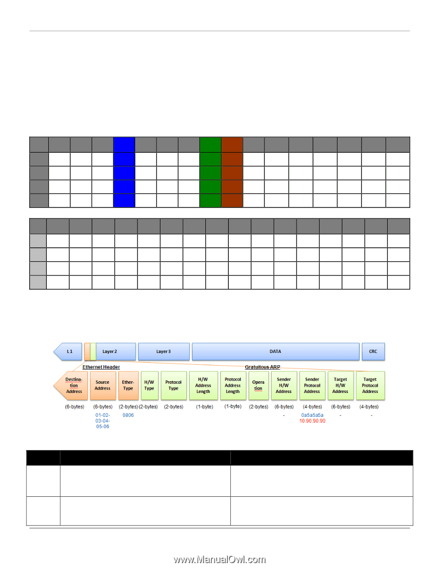
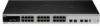
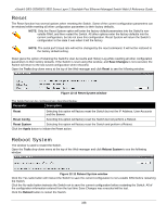
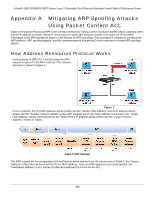
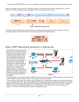
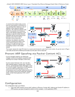
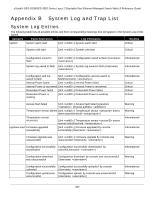
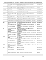
xStack® DES-3528/DES-3552 Series Layer 2 Stackable Fast Ethernet Managed Switch Web UI Reference Guide 2. The switch will deny all other ARP packets which claim they are from the gateway's IP. The design of Packet Content ACL on the Switch enables users to inspect any offset chunk. An offset chunk is a 4-byte block in a HEX format, which is utilized to match the individual field in an Ethernet frame. Each profile is allowed to contain up to a maximum of four offset chunks. Furthermore, only one single profile of Packet Content ACL can be supported per switch. In other words, up to 16 bytes of total offset chunks can be applied to each profile and a switch. Therefore, a careful consideration is needed for planning and configuration of the valuable offset chunks. In Table 6, you will notice that the Offset_Chunk0 starts from the 127th byte and ends at the 128th byte. It also can be found that the offset chunk is scratched from 1 but not zero. Offset Offset Offset Offset Offset Offset Offset Offset Offset Offset Offset Offset Offset Offset Offset Offset Offset Chunk Chunk0 Chunk1 Chunk2 Chunk3 Chunk4 Chunk5 Chunk6 Chunk7 Chunk8 Chunk9 Chunk10 Chunk11 Chunk12 Chunk13 Chunk14 Chunk15 Byte 127 3 7 11 15 19 23 27 31 35 39 43 47 51 55 59 Byte 128 4 8 12 16 20 24 28 32 36 40 44 48 52 56 60 Byte 1 5 9 13 17 21 25 29 33 37 41 45 49 53 57 61 Byte 2 6 10 14 18 22 26 30 34 38 42 46 50 54 58 62 Offset Offset Offset Offset Offset Offset Offset Offset Offset Offset Offset Offset Offset Offset Offset Offset Offset Chunk Chunk16 Chunk17 Chunk18 Chunk19 Chunk20 Chunk21 Chunk22 Chunk23 Chunk24 Chunk25 Chunk26 Chunk27 Chunk28 Chunk29 Chunk30 Chunk31 Byte 63 67 71 75 79 83 87 91 95 99 103 107 111 115 119 123 Byte 64 68 72 76 80 84 88 92 96 100 104 108 112 116 120 124 Byte 65 69 73 77 81 85 89 93 97 101 105 109 113 117 121 125 Byte 66 70 74 78 82 86 90 94 98 102 106 110 114 118 122 126 Table 6. Chunk and Packet Offset The following table indicates a completed ARP packet contained in Ethernet frame which is the pattern for the calculation of packet offset. Table 5 A Completed ARP Packet Contained in an Ethernet Frame Command Description Step 1: create access_profile profile_id 1 profile_name 1 ethernet source_mac FF-FF-FF-FF-FF-FF ethernet_type Create access profile 1 to match Ethernet Type and Source MAC address. Step 2: config access_profile profile_id 1 add access_id 1 ethernet source_mac 01-02-03-04-05-06 ethernet_type 343 Configure access profile 1 Only if the gateway's ARP packet that contains the
-
 1
1 -
2
-
3
-
4
-
5
-
6
-
7
-
8
-
9
-
10
-
11
-
12
-
13
-
14
-
15
-
16
-
17
-
18
-
19
-
20
-
21
-
22
-
23
-
24
-
25
-
26
-
27
-
28
-
29
-
30
-
31
-
32
-
33
-
34
-
35
-
36
-
37
-
38
-
39
-
40
-
41
-
42
-
43
-
44
-
45
-
46
-
47
-
48
-
49
-
50
-
51
-
52
-
53
-
54
-
55
-
56
-
57
-
58
-
59
-
60
-
61
-
62
-
63
-
64
-
65
-
66
-
67
-
68
-
69
-
70
-
71
-
72
-
73
-
74
-
75
-
76
-
77
-
78
-
79
-
80
-
81
-
82
-
83
-
84
-
85
-
86
-
87
-
88
-
89
-
90
-
91
-
92
-
93
-
94
-
95
-
96
-
97
-
98
-
99
-
100
-
101
-
102
-
103
-
104
-
105
-
106
-
107
-
108
-
109
-
110
-
111
-
112
-
113
-
114
-
115
-
116
-
117
-
118
-
119
-
120
-
121
-
122
-
123
-
124
-
125
-
126
-
127
-
128
-
129
-
130
-
131
-
132
-
133
-
134
-
135
-
136
-
137
-
138
-
139
-
140
-
141
-
142
-
143
-
144
-
145
-
146
-
147
-
148
-
149
-
150
-
151
-
152
-
153
-
154
-
155
-
156
-
157
-
158
-
159
-
160
-
161
-
162
-
163
-
164
-
165
-
166
-
167
-
168
-
169
-
170
-
171
-
172
-
173
-
174
-
175
-
176
-
177
-
178
-
179
-
180
-
181
-
182
-
183
-
184
-
185
-
186
-
187
-
188
-
189
-
190
-
191
-
192
-
193
-
194
-
195
-
196
-
197
-
198
-
199
-
200
-
201
-
202
-
203
-
204
-
205
-
206
-
207
-
208
-
209
-
210
-
211
-
212
-
213
-
214
-
215
-
216
-
217
-
218
-
219
-
220
-
221
-
222
-
223
-
224
-
225
-
226
-
227
-
228
-
229
-
230
-
231
-
232
-
233
-
234
-
235
-
236
-
237
-
238
-
239
-
240
-
241
-
242
-
243
-
244
-
245
-
246
-
247
-
248
-
249
-
250
-
251
-
252
-
253
-
254
-
255
-
256
-
257
-
258
-
259
-
260
-
261
-
262
-
263
-
264
-
265
-
266
-
267
-
268
-
269
-
270
-
271
-
272
-
273
-
274
-
275
-
276
-
277
-
278
-
279
-
280
-
281
-
282
-
283
-
284
-
285
-
286
-
287
-
288
-
289
-
290
-
291
-
292
-
293
-
294
-
295
-
296
-
297
-
298
-
299
-
300
-
301
-
302
-
303
-
304
-
305
-
306
-
307
-
308
-
309
-
310
-
311
-
312
-
313
-
314
-
315
-
316
-
317
-
318
-
319
-
320
-
321
-
322
-
323
-
324
-
325
-
326
-
327
-
328
-
329
-
330
-
331
-
332
-
333
-
334
-
335
-
336
-
337
-
338
-
339
-
340
-
341
-
342
-
343
-
344
-
345
-
346
-
 347
347 -
 348
348 -
 349
349 -
 350
350 -
 351
351 -
 352
352 -
 353
353 -
 354
354 -
 355
355 -
 356
356 -
 357
357 -
358
-
359
-
360
-
361
-
362
-
363
-
364
-
365
-
366
-
367
 |
 |