D-Link DES-3528 Product Manual - Page 193
CPU Access Profile List, CPU Access Profile List window
 |
UPC - 790069314346
View all D-Link DES-3528 manuals
Add to My Manuals
Save this manual to your list of manuals |
Page 193 highlights
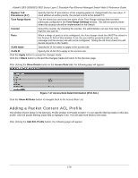
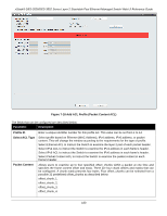
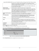
xStack® DES-3528/DES-3552 Series Layer 2 Stackable Fast Ethernet Managed Switch Web UI Reference Guide CPU Access Profile List Due to a chipset limitation and needed extra switch security, the Switch incorporates CPU Interface filtering. This added feature increases the running security of the Switch by enabling the user to create a list of access rules for packets destined for the Switch's CPU interface. Employed similarly to the Access Profile feature previously mentioned, CPU interface filtering examines Ethernet, IP and Packet Content Mask packet headers destined for the CPU and will either forward them or filter them, based on the user's implementation. As an added feature for the CPU Filtering, the Switch allows the CPU filtering mechanism to be enabled or disabled globally, permitting the user to create various lists of rules without immediately enabling them. NOTE: CPU Interface Filtering is used to control traffic access to the Switch directly such as protocols transition or management access. A CPU interface filtering rule won't impact normal L2/3 traffic forwarding. However, a improper CPU interface filtering rule may cause the network to become unstable. To view CPU Access Profile List window, click ACL > CPU Access Profile List, as shown below: Creating an access profile for the CPU is divided into two basic parts. The first is to specify which part or parts of a frame the Switch will examine, such as the MAC source address or the IP destination address. The second part is entering the criteria the Switch will use to determine what to do with the frame. The entire process is described below. Users may globally enable or disable the CPU Interface Filtering State mechanism by using the radio buttons to change the running state. Choose Enabled to enable CPU packets to be scrutinized by the Switch and Disabled to disallow this scrutiny. Figure 7-23 CPU Access Profile List window The fields that can be configured are described below: Parameter Description CPU Interface Filtering State Enable or disable the CPU interface filtering state. Click the Apply button to accept the changes made. Click the Add CPU ACL Profile button to add an entry to the CPU ACL Profile List. Click the Delete All button to remove all access profiles from this table. Click the Show Details button to display the information of the specific profile ID entry. Click the Add/View Rules button to view or add CPU ACL rules within the specified profile ID. Click the Delete button to remove the specific entry. There are four Add CPU ACL Profile windows; 184
-
 1
1 -
2
-
3
-
4
-
5
-
6
-
7
-
8
-
9
-
10
-
11
-
12
-
13
-
14
-
15
-
16
-
17
-
18
-
19
-
20
-
21
-
22
-
23
-
24
-
25
-
26
-
27
-
28
-
29
-
30
-
31
-
32
-
33
-
34
-
35
-
36
-
37
-
38
-
39
-
40
-
41
-
42
-
43
-
44
-
45
-
46
-
47
-
48
-
49
-
50
-
51
-
52
-
53
-
54
-
55
-
56
-
57
-
58
-
59
-
60
-
61
-
62
-
63
-
64
-
65
-
66
-
67
-
68
-
69
-
70
-
71
-
72
-
73
-
74
-
75
-
76
-
77
-
78
-
79
-
80
-
81
-
82
-
83
-
84
-
85
-
86
-
87
-
88
-
89
-
90
-
91
-
92
-
93
-
94
-
95
-
96
-
97
-
98
-
99
-
100
-
101
-
102
-
103
-
104
-
105
-
106
-
107
-
108
-
109
-
110
-
111
-
112
-
113
-
114
-
115
-
116
-
117
-
118
-
119
-
120
-
121
-
122
-
123
-
124
-
125
-
126
-
127
-
128
-
129
-
130
-
131
-
132
-
133
-
134
-
135
-
136
-
137
-
138
-
139
-
140
-
141
-
142
-
143
-
144
-
145
-
146
-
147
-
148
-
149
-
150
-
151
-
152
-
153
-
154
-
155
-
156
-
157
-
158
-
159
-
160
-
161
-
162
-
163
-
164
-
165
-
166
-
167
-
168
-
169
-
170
-
171
-
172
-
173
-
174
-
175
-
176
-
177
-
178
-
179
-
180
-
181
-
182
-
183
-
184
-
185
-
186
-
187
-
 188
188 -
 189
189 -
 190
190 -
 191
191 -
 192
192 -
 193
193 -
 194
194 -
 195
195 -
 196
196 -
 197
197 -
 198
198 -
199
-
200
-
201
-
202
-
203
-
204
-
205
-
206
-
207
-
208
-
209
-
210
-
211
-
212
-
213
-
214
-
215
-
216
-
217
-
218
-
219
-
220
-
221
-
222
-
223
-
224
-
225
-
226
-
227
-
228
-
229
-
230
-
231
-
232
-
233
-
234
-
235
-
236
-
237
-
238
-
239
-
240
-
241
-
242
-
243
-
244
-
245
-
246
-
247
-
248
-
249
-
250
-
251
-
252
-
253
-
254
-
255
-
256
-
257
-
258
-
259
-
260
-
261
-
262
-
263
-
264
-
265
-
266
-
267
-
268
-
269
-
270
-
271
-
272
-
273
-
274
-
275
-
276
-
277
-
278
-
279
-
280
-
281
-
282
-
283
-
284
-
285
-
286
-
287
-
288
-
289
-
290
-
291
-
292
-
293
-
294
-
295
-
296
-
297
-
298
-
299
-
300
-
301
-
302
-
303
-
304
-
305
-
306
-
307
-
308
-
309
-
310
-
311
-
312
-
313
-
314
-
315
-
316
-
317
-
318
-
319
-
320
-
321
-
322
-
323
-
324
-
325
-
326
-
327
-
328
-
329
-
330
-
331
-
332
-
333
-
334
-
335
-
336
-
337
-
338
-
339
-
340
-
341
-
342
-
343
-
344
-
345
-
346
-
347
-
348
-
349
-
350
-
351
-
352
-
353
-
354
-
355
-
356
-
357
-
358
-
359
-
360
-
361
-
362
-
363
-
364
-
365
-
366
-
367
 |
 |