D-Link DES-3528 Product Manual - Page 218
Authenticator State, Limitations Using the Guest VLAN
 |
UPC - 790069314346
View all D-Link DES-3528 manuals
Add to My Manuals
Save this manual to your list of manuals |
Page 218 highlights
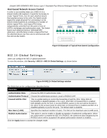
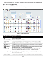
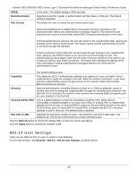
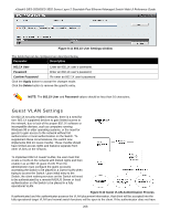
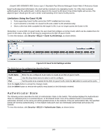
xStack® DES-3528/DES-3552 Series Layer 2 Stackable Fast Ethernet Managed Switch Web UI Reference Guide target VLAN placement information, the client will be returned to its originating VLAN. Yet, if the client is denied authentication by the authenticator, it will be placed in the Guest VLAN where it has limited rights and access. The adjacent figure should give the user a better understanding of the Guest VLAN process. Limitations Using the Guest VLAN 1. Ports supporting Guest VLANs cannot be GVRP enabled and vice versa. 2. A port cannot be a member of a Guest VLAN and a static VLAN simultaneously. 3. Once a client has been accepted into the target VLAN, it can no longer access the Guest VLAN. Remember, to set an 802.1X guest VLAN, the user must first configure a normal VLAN, which can be enabled here for guest VLAN status. Only one VLAN may be assigned as the 802.1X guest VLAN. To view this window, click Security > 802.1X > Guest VLAN Settings, as shown below: Figure 8-13 Guest VLAN Settings window The fields that can be configured are described below: Parameter Description VLAN Name Enter the pre-configured VLAN name to create as an 802.1X guest VLAN. Unit Use the drop-down menu to select a unit to configure. Port Set the ports to be enabled for the 802.1X guest VLAN. Click the All button to select all the ports. Click the Apply button to accept the changes made. Click the Delete button to remove the specific entry based on the information entered. Authenticator State The following section describes the 802.1X Authenticator State on the Switch. This window displays the Authenticator State for individual ports on a selected device. In Port-based mode if one of the attached hosts is successfully authorized, all hosts on the same port will be granted access to the network. If the port authorization fails, the specified port(s) will continue authenticating. In Host-based mode each user can individually authenticate and access the network. To view this window, click Security > 802.1X > Authenticator State, as shown below: 209
-
 1
1 -
2
-
3
-
4
-
5
-
6
-
7
-
8
-
9
-
10
-
11
-
12
-
13
-
14
-
15
-
16
-
17
-
18
-
19
-
20
-
21
-
22
-
23
-
24
-
25
-
26
-
27
-
28
-
29
-
30
-
31
-
32
-
33
-
34
-
35
-
36
-
37
-
38
-
39
-
40
-
41
-
42
-
43
-
44
-
45
-
46
-
47
-
48
-
49
-
50
-
51
-
52
-
53
-
54
-
55
-
56
-
57
-
58
-
59
-
60
-
61
-
62
-
63
-
64
-
65
-
66
-
67
-
68
-
69
-
70
-
71
-
72
-
73
-
74
-
75
-
76
-
77
-
78
-
79
-
80
-
81
-
82
-
83
-
84
-
85
-
86
-
87
-
88
-
89
-
90
-
91
-
92
-
93
-
94
-
95
-
96
-
97
-
98
-
99
-
100
-
101
-
102
-
103
-
104
-
105
-
106
-
107
-
108
-
109
-
110
-
111
-
112
-
113
-
114
-
115
-
116
-
117
-
118
-
119
-
120
-
121
-
122
-
123
-
124
-
125
-
126
-
127
-
128
-
129
-
130
-
131
-
132
-
133
-
134
-
135
-
136
-
137
-
138
-
139
-
140
-
141
-
142
-
143
-
144
-
145
-
146
-
147
-
148
-
149
-
150
-
151
-
152
-
153
-
154
-
155
-
156
-
157
-
158
-
159
-
160
-
161
-
162
-
163
-
164
-
165
-
166
-
167
-
168
-
169
-
170
-
171
-
172
-
173
-
174
-
175
-
176
-
177
-
178
-
179
-
180
-
181
-
182
-
183
-
184
-
185
-
186
-
187
-
188
-
189
-
190
-
191
-
192
-
193
-
194
-
195
-
196
-
197
-
198
-
199
-
200
-
201
-
202
-
203
-
204
-
205
-
206
-
207
-
208
-
209
-
210
-
211
-
212
-
 213
213 -
 214
214 -
 215
215 -
 216
216 -
 217
217 -
 218
218 -
 219
219 -
 220
220 -
 221
221 -
 222
222 -
 223
223 -
224
-
225
-
226
-
227
-
228
-
229
-
230
-
231
-
232
-
233
-
234
-
235
-
236
-
237
-
238
-
239
-
240
-
241
-
242
-
243
-
244
-
245
-
246
-
247
-
248
-
249
-
250
-
251
-
252
-
253
-
254
-
255
-
256
-
257
-
258
-
259
-
260
-
261
-
262
-
263
-
264
-
265
-
266
-
267
-
268
-
269
-
270
-
271
-
272
-
273
-
274
-
275
-
276
-
277
-
278
-
279
-
280
-
281
-
282
-
283
-
284
-
285
-
286
-
287
-
288
-
289
-
290
-
291
-
292
-
293
-
294
-
295
-
296
-
297
-
298
-
299
-
300
-
301
-
302
-
303
-
304
-
305
-
306
-
307
-
308
-
309
-
310
-
311
-
312
-
313
-
314
-
315
-
316
-
317
-
318
-
319
-
320
-
321
-
322
-
323
-
324
-
325
-
326
-
327
-
328
-
329
-
330
-
331
-
332
-
333
-
334
-
335
-
336
-
337
-
338
-
339
-
340
-
341
-
342
-
343
-
344
-
345
-
346
-
347
-
348
-
349
-
350
-
351
-
352
-
353
-
354
-
355
-
356
-
357
-
358
-
359
-
360
-
361
-
362
-
363
-
364
-
365
-
366
-
367
 |
 |