D-Link DES-3528 Product Manual - Page 163
Time Interval 5-600, Threshold 0-255000, Traffic Control Type, Traffic Trap Settings
 |
UPC - 790069314346
View all D-Link DES-3528 manuals
Add to My Manuals
Save this manual to your list of manuals |
Page 163 highlights
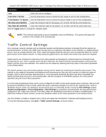
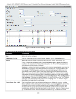
xStack® DES-3528/DES-3552 Series Layer 2 Stackable Fast Ethernet Managed Switch Web UI Reference Guide immediately. Time Interval (5-600) The Time Interval will set the time between Multicast and Broadcast packet counts sent from the Switch's chip to the Traffic Control function. These packet counts are the determining factor in deciding when incoming packets exceed the Threshold value. The Time Interval may be set between 5 and 600 seconds, with a default setting of 5 seconds. Threshold (0-255000) Traffic Control Type Specifies the maximum number of packets per second that will trigger the Traffic Control function to commence. The configurable threshold range is from 0-255000 with a default setting of 131072 packets per second. Specifies the desired Storm Control Type: None, Broadcast, Multicast, Unknown Unicast, Broadcast + Multicast, Broadcast + Unknown Unicast, Multicast + Unknown Unicast, and Broadcast + Multicast + Unknown Unicast. Traffic Trap Settings Enable sending of Storm Trap messages when the type of action taken by the Traffic Control function in handling a Traffic Storm is one of the following: None - Will send no Storm trap warning messages regardless of action taken by the Traffic Control mechanism. Storm Occurred - Will send Storm Trap warning messages upon the occurrence of a Traffic Storm only. Storm Cleared - Will send Storm Trap messages when a Traffic Storm has been cleared by the Switch only. Both - Will send Storm Trap messages when a Traffic Storm has been both detected and cleared by the Switch. This function cannot be implemented in the hardware mode. (When Drop is chosen for the Action parameter) Traffic Log Settings Use the drop-down menu to enable or disable traffic log. Traffic Auto Recover Time (0-65535) Enter a time for traffic auto recovery. Click the Apply button to accept the changes made for each individual section. NOTE: Traffic Control cannot be implemented on ports that are set for Link Aggregation (Port Trunking). NOTE: Ports that are in the Shutdown mode will be seen as Discarding in Spanning Tree windows and implementations though these ports will still be forwarding BPDUs to the Switch's CPU. NOTE: Ports that are in Shutdown Forever mode will be seen as link down in all windows and screens until the user recovers these ports. NOTE: The minimum granularity of storm control on a GE port is 1pps. 154
-
 1
1 -
2
-
3
-
4
-
5
-
6
-
7
-
8
-
9
-
10
-
11
-
12
-
13
-
14
-
15
-
16
-
17
-
18
-
19
-
20
-
21
-
22
-
23
-
24
-
25
-
26
-
27
-
28
-
29
-
30
-
31
-
32
-
33
-
34
-
35
-
36
-
37
-
38
-
39
-
40
-
41
-
42
-
43
-
44
-
45
-
46
-
47
-
48
-
49
-
50
-
51
-
52
-
53
-
54
-
55
-
56
-
57
-
58
-
59
-
60
-
61
-
62
-
63
-
64
-
65
-
66
-
67
-
68
-
69
-
70
-
71
-
72
-
73
-
74
-
75
-
76
-
77
-
78
-
79
-
80
-
81
-
82
-
83
-
84
-
85
-
86
-
87
-
88
-
89
-
90
-
91
-
92
-
93
-
94
-
95
-
96
-
97
-
98
-
99
-
100
-
101
-
102
-
103
-
104
-
105
-
106
-
107
-
108
-
109
-
110
-
111
-
112
-
113
-
114
-
115
-
116
-
117
-
118
-
119
-
120
-
121
-
122
-
123
-
124
-
125
-
126
-
127
-
128
-
129
-
130
-
131
-
132
-
133
-
134
-
135
-
136
-
137
-
138
-
139
-
140
-
141
-
142
-
143
-
144
-
145
-
146
-
147
-
148
-
149
-
150
-
151
-
152
-
153
-
154
-
155
-
156
-
157
-
 158
158 -
 159
159 -
 160
160 -
 161
161 -
 162
162 -
 163
163 -
 164
164 -
 165
165 -
 166
166 -
 167
167 -
 168
168 -
169
-
170
-
171
-
172
-
173
-
174
-
175
-
176
-
177
-
178
-
179
-
180
-
181
-
182
-
183
-
184
-
185
-
186
-
187
-
188
-
189
-
190
-
191
-
192
-
193
-
194
-
195
-
196
-
197
-
198
-
199
-
200
-
201
-
202
-
203
-
204
-
205
-
206
-
207
-
208
-
209
-
210
-
211
-
212
-
213
-
214
-
215
-
216
-
217
-
218
-
219
-
220
-
221
-
222
-
223
-
224
-
225
-
226
-
227
-
228
-
229
-
230
-
231
-
232
-
233
-
234
-
235
-
236
-
237
-
238
-
239
-
240
-
241
-
242
-
243
-
244
-
245
-
246
-
247
-
248
-
249
-
250
-
251
-
252
-
253
-
254
-
255
-
256
-
257
-
258
-
259
-
260
-
261
-
262
-
263
-
264
-
265
-
266
-
267
-
268
-
269
-
270
-
271
-
272
-
273
-
274
-
275
-
276
-
277
-
278
-
279
-
280
-
281
-
282
-
283
-
284
-
285
-
286
-
287
-
288
-
289
-
290
-
291
-
292
-
293
-
294
-
295
-
296
-
297
-
298
-
299
-
300
-
301
-
302
-
303
-
304
-
305
-
306
-
307
-
308
-
309
-
310
-
311
-
312
-
313
-
314
-
315
-
316
-
317
-
318
-
319
-
320
-
321
-
322
-
323
-
324
-
325
-
326
-
327
-
328
-
329
-
330
-
331
-
332
-
333
-
334
-
335
-
336
-
337
-
338
-
339
-
340
-
341
-
342
-
343
-
344
-
345
-
346
-
347
-
348
-
349
-
350
-
351
-
352
-
353
-
354
-
355
-
356
-
357
-
358
-
359
-
360
-
361
-
362
-
363
-
364
-
365
-
366
-
367
 |
 |
