D-Link DES-3528 Product Manual - Page 40
Interface Settings, Management > IP Interface > Interface Settings
 |
UPC - 790069314346
View all D-Link DES-3528 manuals
Add to My Manuals
Save this manual to your list of manuals |
Page 40 highlights
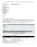
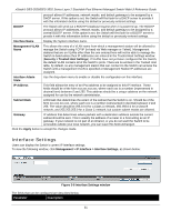
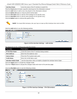
xStack® DES-3528/DES-3552 Series Layer 2 Stackable Fast Ethernet Managed Switch Web UI Reference Guide protocol allows IP addresses, network masks, and default gateways to be assigned by a DHCP server. If this option is set, the Switch will first look for a DHCP server to provide it with this information before using the default or previously entered settings. BOOTP The Switch will send out a BOOTP broadcast request when it is powered up. The BOOTP protocol allows IP addresses, network masks, and default gateways to be assigned by a central BOOTP server. If this option is set, the Switch will first look for a BOOTP server to provide it with this information before using the default or previously entered settings. Interface Name Management VLAN Name Display the System interface name. This allows the entry of a VLAN name from which a management station will be allowed to manage the Switch using TCP/IP (in-band via Web manager or Telnet). Management stations that are on VLANs other than the one entered here will not be able to manage the Switch in-band unless their IP addresses are entered in the Trusted Host Settings window (Security > Trusted Host Settings). If VLANs have not yet been configured for the Switch, the default VLAN contains all of the Switch's ports. There are no entries in the Trusted Host table, by default, so any management station that can connect to the Switch can access the Switch until a management VLAN is specified or Management Station IP addresses are assigned. Interface Admin State IP Address Use the drop-down menu to enable or disable the configuration on this interface. This field allows the entry of an IPv4 address to be assigned to this IP interface. These fields should be of the form xxx.xxx.xxx.xxx, where each xxx is a number (represented in decimal form) between 0 and 255. This address should be a unique address on the network assigned for use by the network administrator. Subnet Mask A Bitmask that determines the extent of the subnet that the Switch is on. Should be of the form xxx.xxx.xxx.xxx, where each xxx is a number (represented in decimal) between 0 and 255. The value should be 255.0.0.0 for a Class A network, 255.255.0.0 for a Class B network, and 255.255.255.0 for a Class C network, but custom subnet masks are allowed. Gateway IP address that determines where packets with a destination address outside the current subnet should be sent. This is usually the address of a router or a host acting as an IP gateway. If your network is not part of an intranet, or you do not want the Switch to be accessible outside your local network, you can leave this field unchanged. Click the Apply button to accept the changes made. Interface Settings Users can display the Switch's current IP interface settings. To view the following window, click Management > IP Interface > Interface Settings, as shown below: Figure 3-8 Interface Settings window The fields that can be configured are described below: Parameter Description 31
-
 1
1 -
2
-
3
-
4
-
5
-
6
-
7
-
8
-
9
-
10
-
11
-
12
-
13
-
14
-
15
-
16
-
17
-
18
-
19
-
20
-
21
-
22
-
23
-
24
-
25
-
26
-
27
-
28
-
29
-
30
-
31
-
32
-
33
-
34
-
 35
35 -
 36
36 -
 37
37 -
 38
38 -
 39
39 -
 40
40 -
 41
41 -
 42
42 -
 43
43 -
 44
44 -
 45
45 -
46
-
47
-
48
-
49
-
50
-
51
-
52
-
53
-
54
-
55
-
56
-
57
-
58
-
59
-
60
-
61
-
62
-
63
-
64
-
65
-
66
-
67
-
68
-
69
-
70
-
71
-
72
-
73
-
74
-
75
-
76
-
77
-
78
-
79
-
80
-
81
-
82
-
83
-
84
-
85
-
86
-
87
-
88
-
89
-
90
-
91
-
92
-
93
-
94
-
95
-
96
-
97
-
98
-
99
-
100
-
101
-
102
-
103
-
104
-
105
-
106
-
107
-
108
-
109
-
110
-
111
-
112
-
113
-
114
-
115
-
116
-
117
-
118
-
119
-
120
-
121
-
122
-
123
-
124
-
125
-
126
-
127
-
128
-
129
-
130
-
131
-
132
-
133
-
134
-
135
-
136
-
137
-
138
-
139
-
140
-
141
-
142
-
143
-
144
-
145
-
146
-
147
-
148
-
149
-
150
-
151
-
152
-
153
-
154
-
155
-
156
-
157
-
158
-
159
-
160
-
161
-
162
-
163
-
164
-
165
-
166
-
167
-
168
-
169
-
170
-
171
-
172
-
173
-
174
-
175
-
176
-
177
-
178
-
179
-
180
-
181
-
182
-
183
-
184
-
185
-
186
-
187
-
188
-
189
-
190
-
191
-
192
-
193
-
194
-
195
-
196
-
197
-
198
-
199
-
200
-
201
-
202
-
203
-
204
-
205
-
206
-
207
-
208
-
209
-
210
-
211
-
212
-
213
-
214
-
215
-
216
-
217
-
218
-
219
-
220
-
221
-
222
-
223
-
224
-
225
-
226
-
227
-
228
-
229
-
230
-
231
-
232
-
233
-
234
-
235
-
236
-
237
-
238
-
239
-
240
-
241
-
242
-
243
-
244
-
245
-
246
-
247
-
248
-
249
-
250
-
251
-
252
-
253
-
254
-
255
-
256
-
257
-
258
-
259
-
260
-
261
-
262
-
263
-
264
-
265
-
266
-
267
-
268
-
269
-
270
-
271
-
272
-
273
-
274
-
275
-
276
-
277
-
278
-
279
-
280
-
281
-
282
-
283
-
284
-
285
-
286
-
287
-
288
-
289
-
290
-
291
-
292
-
293
-
294
-
295
-
296
-
297
-
298
-
299
-
300
-
301
-
302
-
303
-
304
-
305
-
306
-
307
-
308
-
309
-
310
-
311
-
312
-
313
-
314
-
315
-
316
-
317
-
318
-
319
-
320
-
321
-
322
-
323
-
324
-
325
-
326
-
327
-
328
-
329
-
330
-
331
-
332
-
333
-
334
-
335
-
336
-
337
-
338
-
339
-
340
-
341
-
342
-
343
-
344
-
345
-
346
-
347
-
348
-
349
-
350
-
351
-
352
-
353
-
354
-
355
-
356
-
357
-
358
-
359
-
360
-
361
-
362
-
363
-
364
-
365
-
366
-
367
 |
 |