D-Link DES-3528 Product Manual - Page 136
ERPS Settings, G.8032 Terms and Concepts
 |
UPC - 790069314346
View all D-Link DES-3528 manuals
Add to My Manuals
Save this manual to your list of manuals |
Page 136 highlights
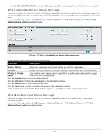
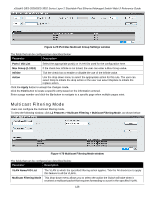
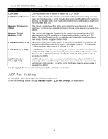
xStack® DES-3528/DES-3552 Series Layer 2 Stackable Fast Ethernet Managed Switch Web UI Reference Guide Forward All Groups - This will instruct the Switch to forward all multicast packets to the specified VLAN. Forward Unregistered Groups - The multicast packets whose destination is a registered multicast group will be forwarded within the range of ports specified above. Filter Unregistered Groups - The multicast packets whose destination is a registered multicast group will be forwarded within the range of ports specified above. Click the Apply button to accept the changes made. Click the Find button to locate a specific entry based on the information entered. Enter a page number and click the Go button to navigate to a specific page when multiple pages exist. ERPS Settings ERPS (Ethernet Ring Protection Switching) is the first industry standard (ITU-T G.8032) for Ethernet ring protection switching. It is achieved by integrating mature Ethernet operations, administration, and maintenance (OAM) * functions and a simple automatic protection switching (APS) protocol for Ethernet ring networks. ERPS provides sub-50ms protection for Ethernet traffic in a ring topology. It ensures that there are no loops formed at the Ethernet layer. One link within a ring will be blocked to avoid a Loop (RPL, Ring Protection Link). When the failure happens, protection switching blocks the failed link and unblocks the RPL. When the failure clears, protection switching blocks the RPL again and unblocks the link on which the failure is cleared. G.8032 Terms and Concepts The ERPS ring is formed by connecting all east and west ports of the switches in the ring. Administrators have to manually configure the blocked port to prevent the loop. See below for a detailed explanation of ERPS terms: RPL (Ring Protection Link) - The link, designated by ERPS mechanism, that is blocked during the Idle state to prevent loops on a Bridged ring. RPL Owner - The node connected to RPL that blocks traffic on RPL during the Idle state and unblocks during the Protected state. R-APS (Ring - Automatic Protection Switching) - Protocol messages defined in Y.1731 and G.8032 used to coordinate the protection actions over the ring through RAPS VLAN (R-APS Channel). RAPS VLAN (R-APS Channel) - A separate ring-wide VLAN for transmission of R-APS messages. Protected VLAN - The service traffic VLANs for transmission of normal network traffic. Ring Topology ERPS supports Ethernet ring topology, as shown in the diagram below: • Single ring (a) • Two single rings with a shared node (b) • Multi-ring: Rings share a common link and nodes (c) Figure 4-80 Ethernet ring topologies supported by ERPS 127
-
 1
1 -
2
-
3
-
4
-
5
-
6
-
7
-
8
-
9
-
10
-
11
-
12
-
13
-
14
-
15
-
16
-
17
-
18
-
19
-
20
-
21
-
22
-
23
-
24
-
25
-
26
-
27
-
28
-
29
-
30
-
31
-
32
-
33
-
34
-
35
-
36
-
37
-
38
-
39
-
40
-
41
-
42
-
43
-
44
-
45
-
46
-
47
-
48
-
49
-
50
-
51
-
52
-
53
-
54
-
55
-
56
-
57
-
58
-
59
-
60
-
61
-
62
-
63
-
64
-
65
-
66
-
67
-
68
-
69
-
70
-
71
-
72
-
73
-
74
-
75
-
76
-
77
-
78
-
79
-
80
-
81
-
82
-
83
-
84
-
85
-
86
-
87
-
88
-
89
-
90
-
91
-
92
-
93
-
94
-
95
-
96
-
97
-
98
-
99
-
100
-
101
-
102
-
103
-
104
-
105
-
106
-
107
-
108
-
109
-
110
-
111
-
112
-
113
-
114
-
115
-
116
-
117
-
118
-
119
-
120
-
121
-
122
-
123
-
124
-
125
-
126
-
127
-
128
-
129
-
130
-
 131
131 -
 132
132 -
 133
133 -
 134
134 -
 135
135 -
 136
136 -
 137
137 -
 138
138 -
 139
139 -
 140
140 -
 141
141 -
142
-
143
-
144
-
145
-
146
-
147
-
148
-
149
-
150
-
151
-
152
-
153
-
154
-
155
-
156
-
157
-
158
-
159
-
160
-
161
-
162
-
163
-
164
-
165
-
166
-
167
-
168
-
169
-
170
-
171
-
172
-
173
-
174
-
175
-
176
-
177
-
178
-
179
-
180
-
181
-
182
-
183
-
184
-
185
-
186
-
187
-
188
-
189
-
190
-
191
-
192
-
193
-
194
-
195
-
196
-
197
-
198
-
199
-
200
-
201
-
202
-
203
-
204
-
205
-
206
-
207
-
208
-
209
-
210
-
211
-
212
-
213
-
214
-
215
-
216
-
217
-
218
-
219
-
220
-
221
-
222
-
223
-
224
-
225
-
226
-
227
-
228
-
229
-
230
-
231
-
232
-
233
-
234
-
235
-
236
-
237
-
238
-
239
-
240
-
241
-
242
-
243
-
244
-
245
-
246
-
247
-
248
-
249
-
250
-
251
-
252
-
253
-
254
-
255
-
256
-
257
-
258
-
259
-
260
-
261
-
262
-
263
-
264
-
265
-
266
-
267
-
268
-
269
-
270
-
271
-
272
-
273
-
274
-
275
-
276
-
277
-
278
-
279
-
280
-
281
-
282
-
283
-
284
-
285
-
286
-
287
-
288
-
289
-
290
-
291
-
292
-
293
-
294
-
295
-
296
-
297
-
298
-
299
-
300
-
301
-
302
-
303
-
304
-
305
-
306
-
307
-
308
-
309
-
310
-
311
-
312
-
313
-
314
-
315
-
316
-
317
-
318
-
319
-
320
-
321
-
322
-
323
-
324
-
325
-
326
-
327
-
328
-
329
-
330
-
331
-
332
-
333
-
334
-
335
-
336
-
337
-
338
-
339
-
340
-
341
-
342
-
343
-
344
-
345
-
346
-
347
-
348
-
349
-
350
-
351
-
352
-
353
-
354
-
355
-
356
-
357
-
358
-
359
-
360
-
361
-
362
-
363
-
364
-
365
-
366
-
367
 |
 |