Icom IC-R9500 Instruction Manual - Page 12
Front panel
 |
View all Icom IC-R9500 manuals
Add to My Manuals
Save this manual to your list of manuals |
Page 12 highlights
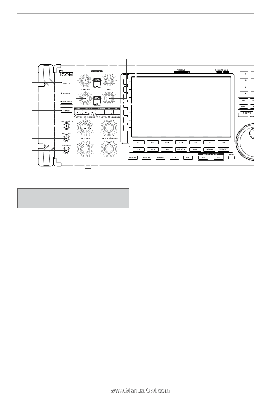
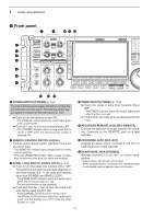
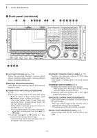
1 PANEL DESCRIPTION ■ Front panel i o !0 !1 !2 q w e r t y u !3 !4 !5 q POWER SWITCH [POWER] (p. 3-2) Turn the internal power supply ON before turning the unit ON from the front panel. The internal power supply switch is located on the rear panel. (p. 3-2) ➥ Push to turn the receiver power ON. • The [POWER] indicator above this switch lights green when powered ON. ➥ Push for 1 sec. to turn the receiver power OFF. • The [POWER] indicator lights orange when the receiver is OFF when the internal power supply is switched ON. w REMOTE CONTROL SWITCH [LOCAL] Push to cancel remote control operation from a PC via a CI-V data. • The [REMOTE] indicator lights orange while in remote control operation. • When the [REMOTE] indicator lights orange, all dials, keys or switches other than this switch are disabled. e PANEL LOCK SWITCH [PANEL LOCK] (p. 9-2) ➥ Push to turn the panel lock function ON or OFF. The panel lock function locks all dials (depends on set mode setting on p. 11-10), keys and switches other than [POWER] and [PANEL LOCK]. • The [PANEL LOCK] indicator above this switch lights green when the panel lock is in use. • The dial lock function is also available. ➥ Push and hold for 1 sec. to turn the panel lock with display sleep function ON. • Pushing [PANEL LOCK] turns this function OFF. • The [PANEL LOCK] indicator above this switch lights green and the display turns OFF when the sleep function is in use. r TIMER SWITCH [TIMER] (p. 10-3) ➥ Turns the sleep or daily timer function ON or OFF. • The [TIMER] indicator above this switch lights green when the timer is in use. ➥ Enters timer set mode when pushed and held for 1 sec. t RECORDER REMOTE JACK [REC REMOTE] Controls the operation of a tape recorder for recording. Connects to the REMOTE jack on a tape recorder. y RECORDER JACK [REC OUT] Outputs an audio signal. Connect to the AUX or LINE IN jack on a tape recorder. u HEADPHONE JACK [PHONES] Accepts standard 3.5 (d) mm (1⁄8) stereo headphones. • Output power: 40 mW with an 8 Ω load. • When headphones are connected, the internal speaker or connected external speaker does not function. 1-2
-
 1
1 -
2
-
3
-
4
-
5
-
6
-
 7
7 -
 8
8 -
 9
9 -
 10
10 -
 11
11 -
 12
12 -
 13
13 -
 14
14 -
 15
15 -
 16
16 -
 17
17 -
18
-
19
-
20
-
21
-
22
-
23
-
24
-
25
-
26
-
27
-
28
-
29
-
30
-
31
-
32
-
33
-
34
-
35
-
36
-
37
-
38
-
39
-
40
-
41
-
42
-
43
-
44
-
45
-
46
-
47
-
48
-
49
-
50
-
51
-
52
-
53
-
54
-
55
-
56
-
57
-
58
-
59
-
60
-
61
-
62
-
63
-
64
-
65
-
66
-
67
-
68
-
69
-
70
-
71
-
72
-
73
-
74
-
75
-
76
-
77
-
78
-
79
-
80
-
81
-
82
-
83
-
84
-
85
-
86
-
87
-
88
-
89
-
90
-
91
-
92
-
93
-
94
-
95
-
96
-
97
-
98
-
99
-
100
-
101
-
102
-
103
-
104
-
105
-
106
-
107
-
108
-
109
-
110
-
111
-
112
-
113
-
114
-
115
-
116
-
117
-
118
-
119
-
120
-
121
-
122
-
123
-
124
-
125
-
126
-
127
-
128
-
129
-
130
-
131
-
132
-
133
-
134
-
135
-
136
-
137
-
138
-
139
-
140
-
141
-
142
-
143
-
144
-
145
-
146
-
147
-
148
-
149
-
150
-
151
-
152
-
153
-
154
-
155
-
156
-
157
-
158
-
159
-
160
-
161
-
162
-
163
-
164
-
165
-
166
-
167
-
168
-
169
-
170
-
171
-
172
-
173
-
174
-
175
-
176
-
177
-
178
-
179
-
180
-
181
-
182
-
183
-
184
-
185
-
186
-
187
-
188
-
189
-
190
-
191
-
192
-
193
-
194
 |
 |