Icom IC-R9500 Instruction Manual - Page 21
S/p Dif Output Terminal [s/p Dif Out]
 |
View all Icom IC-R9500 manuals
Add to My Manuals
Save this manual to your list of manuals |
Page 21 highlights
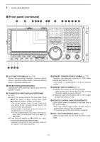
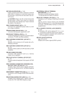
1 PANEL DESCRIPTION !5 FUSE HOLDER [FUSE] (p. 12-8) Holds a 4 A fuse (100 V/120 V versions) or 2 A fuse (230 V/240 V versions) for internal AC power supply protection. Cuts off the AC input when over-current occurs. CAUTION: Always use the correct fuse for AC input power. Using a fuse rated for a different input power may damege your house electrical system or the receiver. !6 AC POWER SOCKET [AC] (p. 2-5) Connects the supplied AC power cable to an AC line-voltage receptacle. !7 MAIN POWER SWITCH [I/O] (p. 3-2) Turns the internal power supply ON or OFF. !8 GROUND TERMINAL [GND] (p. 2-2) Connect this terminal to a ground to prevent electrical shocks, TVI, BCI and other problems. !9 HF ANTENNA CONNECTOR 1 [HF ANT 1] (p. 2-5) Accepts a 50 Ω antenna for HF bands with a PL259 plug connector. @0 HF ANTENNA CONNECTOR 2 [HF ANT 2] (p. 2-5) Accepts a 500 Ω antenna for HF band with an RCA connector. @1 USB CONNECTOR [USB] Connects USB equipment such as a memory media, hub or keyboard. @2 S/P DIF OUTPUT TERMINAL [S/P DIF OUT] (p. 2-7) Connects external equipment that supports S/P DIF output. @3 HF ANTENNA CONNECTOR 3/ANTENNA CONNECTOR 1 [ANT 1/HF ANT 3] (p. 2-5) Accepts a 50 Ω antenna with a Type-N connector. Covers the HF bands and 30-1150 MHz frequency range. @4 ETHERNET CONNECTOR [LAN] (pgs. 2-7, 15-6) Connects to a PC through a LAN (Local Area Network). @5 ANTENNA CONNECTOR 2 [ANT 2] (p. 2-5) Accepts a 50 Ω antenna with a Type-N connector. Covers the 1150-3335 MHz frequency range. @6 EXTERNAL DISPLAY TERMINAL [EXT-DISPLAY] (p. 2-10) Connects to an external display monitor. • At least 800×600 pixel display is necessary. @7 RS-232C TERMINAL [RS-232C] (p. 2-6) Connects to a PC using a D-sub 9-pin RS-232C cable. Can be used for remote control of the IC-R9500 without the optional CT-17, or the FSK decoded signal output. The [RS-232C] interface is wired as a modem (DCE). @8 CI-V REMOTE CONTROL JACK [REMOTE] (p. 2-6) ➥ Connects a PC via the optional CT-17 CI-V LEVEL CONVERTER for external control of the receiver. ➥ Used for transceive operation with another Icom CI-V transceiver or receiver. @9 DATA SOCKET [DATA IN] (pgs. 2-10, 2-12) Outputs LCD monitor signals (NTSC system). 1-11
-
 1
1 -
2
-
3
-
4
-
5
-
6
-
7
-
8
-
9
-
10
-
11
-
12
-
13
-
14
-
15
-
 16
16 -
 17
17 -
 18
18 -
 19
19 -
 20
20 -
 21
21 -
 22
22 -
 23
23 -
 24
24 -
 25
25 -
 26
26 -
27
-
28
-
29
-
30
-
31
-
32
-
33
-
34
-
35
-
36
-
37
-
38
-
39
-
40
-
41
-
42
-
43
-
44
-
45
-
46
-
47
-
48
-
49
-
50
-
51
-
52
-
53
-
54
-
55
-
56
-
57
-
58
-
59
-
60
-
61
-
62
-
63
-
64
-
65
-
66
-
67
-
68
-
69
-
70
-
71
-
72
-
73
-
74
-
75
-
76
-
77
-
78
-
79
-
80
-
81
-
82
-
83
-
84
-
85
-
86
-
87
-
88
-
89
-
90
-
91
-
92
-
93
-
94
-
95
-
96
-
97
-
98
-
99
-
100
-
101
-
102
-
103
-
104
-
105
-
106
-
107
-
108
-
109
-
110
-
111
-
112
-
113
-
114
-
115
-
116
-
117
-
118
-
119
-
120
-
121
-
122
-
123
-
124
-
125
-
126
-
127
-
128
-
129
-
130
-
131
-
132
-
133
-
134
-
135
-
136
-
137
-
138
-
139
-
140
-
141
-
142
-
143
-
144
-
145
-
146
-
147
-
148
-
149
-
150
-
151
-
152
-
153
-
154
-
155
-
156
-
157
-
158
-
159
-
160
-
161
-
162
-
163
-
164
-
165
-
166
-
167
-
168
-
169
-
170
-
171
-
172
-
173
-
174
-
175
-
176
-
177
-
178
-
179
-
180
-
181
-
182
-
183
-
184
-
185
-
186
-
187
-
188
-
189
-
190
-
191
-
192
-
193
-
194
 |
 |