Icom IC-R9500 Instruction Manual - Page 73
Scope set mode continued
 |
View all Icom IC-R9500 manuals
Add to My Manuals
Save this manual to your list of manuals |
Page 73 highlights
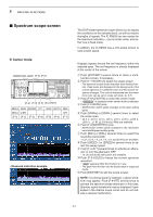
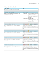
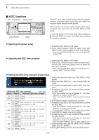
5 RECEIVE FUNCTIONS D Scope set mode (continued) Max Hold ON Turn the peak level holding function ON or OFF. CENTER Type Display Select the center frequency of the spectrum scope indication (center mode only). Filter Center • Filter center : Shows the selected filter's center frequency at the center. • Carrier Point Center : Shows the selected operating mode carrier point frequency at the center. • Carrier Point Center (Abs. Freq.) : In addition to the carrier point center setting above, the actual frequency is displayed at the bottom of the scope. Waveform Color (Current) Set the waveform color for the currently received signals. 161 185 221 • The color is set in RGB format. • Push [F-3•Ω ≈] to select R (Red), G (Green) and B (Blue), and rotate the ratio from 0 to 255 range. • The set color is indicated in the box beside the RGB scale. Waveform Color (Max Hold) Set the waveform color for the receiving signals maximum level. 130 66 176 • The color is set in RGB format. • Push [F-3•Ω ≈] to select R (Red), G (Green) and B (Blue), and rotate the ratio from 0 to 255 range. • The set color is indicated in the box beside the RGB scale. Marker Color (RX) Set the marker color for the displayed frequency while the fix mode. 255 150 50 • The color is set in RGB format. • Push [F-3•Ω ≈] to select R (Red), G (Green) and B (Blue), and rotate the ratio from 0 to 255 range. • The set color is indicated in the box beside the RGB scale. Marker Color (Peak) Set the marker color for the peak frequency of the receiving signals. 255 0 0 • The color is set in RGB format. • Push [F-3•Ω ≈] to select R (Red), G (Green) and B (Blue), and rotate the ratio from 0 to 255 range. • The set color is indicated in the box beside the RGB scale. 5-7
-
 1
1 -
2
-
3
-
4
-
5
-
6
-
7
-
8
-
9
-
10
-
11
-
12
-
13
-
14
-
15
-
16
-
17
-
18
-
19
-
20
-
21
-
22
-
23
-
24
-
25
-
26
-
27
-
28
-
29
-
30
-
31
-
32
-
33
-
34
-
35
-
36
-
37
-
38
-
39
-
40
-
41
-
42
-
43
-
44
-
45
-
46
-
47
-
48
-
49
-
50
-
51
-
52
-
53
-
54
-
55
-
56
-
57
-
58
-
59
-
60
-
61
-
62
-
63
-
64
-
65
-
66
-
67
-
 68
68 -
 69
69 -
 70
70 -
 71
71 -
 72
72 -
 73
73 -
 74
74 -
 75
75 -
 76
76 -
 77
77 -
 78
78 -
79
-
80
-
81
-
82
-
83
-
84
-
85
-
86
-
87
-
88
-
89
-
90
-
91
-
92
-
93
-
94
-
95
-
96
-
97
-
98
-
99
-
100
-
101
-
102
-
103
-
104
-
105
-
106
-
107
-
108
-
109
-
110
-
111
-
112
-
113
-
114
-
115
-
116
-
117
-
118
-
119
-
120
-
121
-
122
-
123
-
124
-
125
-
126
-
127
-
128
-
129
-
130
-
131
-
132
-
133
-
134
-
135
-
136
-
137
-
138
-
139
-
140
-
141
-
142
-
143
-
144
-
145
-
146
-
147
-
148
-
149
-
150
-
151
-
152
-
153
-
154
-
155
-
156
-
157
-
158
-
159
-
160
-
161
-
162
-
163
-
164
-
165
-
166
-
167
-
168
-
169
-
170
-
171
-
172
-
173
-
174
-
175
-
176
-
177
-
178
-
179
-
180
-
181
-
182
-
183
-
184
-
185
-
186
-
187
-
188
-
189
-
190
-
191
-
192
-
193
-
194
 |
 |
