Icom IC-R9500 Instruction Manual - Page 28
TV jumper cable connection except for USA versions, Carrying handle attachment, Rack mounting handle
 |
View all Icom IC-R9500 manuals
Add to My Manuals
Save this manual to your list of manuals |
Page 28 highlights
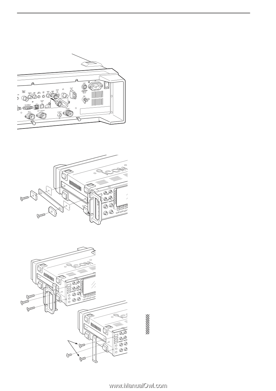
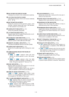
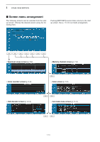
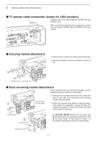
2 INSTALLATION AND CONNECTIONS ■ TV jumper cable connection (except for USA versions) Connect the RCA cable between [VIDEO IN] and [VIDEO OUT]. When connecting external video equipment, connect the unit between [VIDEO IN] and [VIDEO OUT] connectors. ■ Carrying handle attachment q Remove the 2 screws from side panel for both side. w Attach the supplied Carrying handles as shown at left. FH M4×16 mm FH: Flat head ■ Rack mounting handle detachment When removing the rack mounting handles, use the supplied screws for attach the side plates. q Remove the 6 screws from the rack mounting han- dles for both side. And remove the rack mounting handles and side plates. FH: Flat head q PH: Pan head w Attach the removed side plates to original position, then tighten the supplied 4 screws (FH M4×12). Tighten the supplied 2 screw (PH M4×8) for hiding screw holes for both side. FH M4×16 mm w FH M4×12 mm CAUTION: NEVER replace the any other than specified screws for side plate atachment or hiding screw holes. If long screw is used, it is caused to damage the receiver's inside board. PH M4×8 mm 2-4
-
 1
1 -
2
-
3
-
4
-
5
-
6
-
7
-
8
-
9
-
10
-
11
-
12
-
13
-
14
-
15
-
16
-
17
-
18
-
19
-
20
-
21
-
22
-
 23
23 -
 24
24 -
 25
25 -
 26
26 -
 27
27 -
 28
28 -
 29
29 -
 30
30 -
 31
31 -
 32
32 -
 33
33 -
34
-
35
-
36
-
37
-
38
-
39
-
40
-
41
-
42
-
43
-
44
-
45
-
46
-
47
-
48
-
49
-
50
-
51
-
52
-
53
-
54
-
55
-
56
-
57
-
58
-
59
-
60
-
61
-
62
-
63
-
64
-
65
-
66
-
67
-
68
-
69
-
70
-
71
-
72
-
73
-
74
-
75
-
76
-
77
-
78
-
79
-
80
-
81
-
82
-
83
-
84
-
85
-
86
-
87
-
88
-
89
-
90
-
91
-
92
-
93
-
94
-
95
-
96
-
97
-
98
-
99
-
100
-
101
-
102
-
103
-
104
-
105
-
106
-
107
-
108
-
109
-
110
-
111
-
112
-
113
-
114
-
115
-
116
-
117
-
118
-
119
-
120
-
121
-
122
-
123
-
124
-
125
-
126
-
127
-
128
-
129
-
130
-
131
-
132
-
133
-
134
-
135
-
136
-
137
-
138
-
139
-
140
-
141
-
142
-
143
-
144
-
145
-
146
-
147
-
148
-
149
-
150
-
151
-
152
-
153
-
154
-
155
-
156
-
157
-
158
-
159
-
160
-
161
-
162
-
163
-
164
-
165
-
166
-
167
-
168
-
169
-
170
-
171
-
172
-
173
-
174
-
175
-
176
-
177
-
178
-
179
-
180
-
181
-
182
-
183
-
184
-
185
-
186
-
187
-
188
-
189
-
190
-
191
-
192
-
193
-
194
 |
 |