Icom IC-R9500 Instruction Manual - Page 31
Rear panel-2
 |
View all Icom IC-R9500 manuals
Add to My Manuals
Save this manual to your list of manuals |
Page 31 highlights
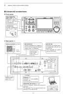
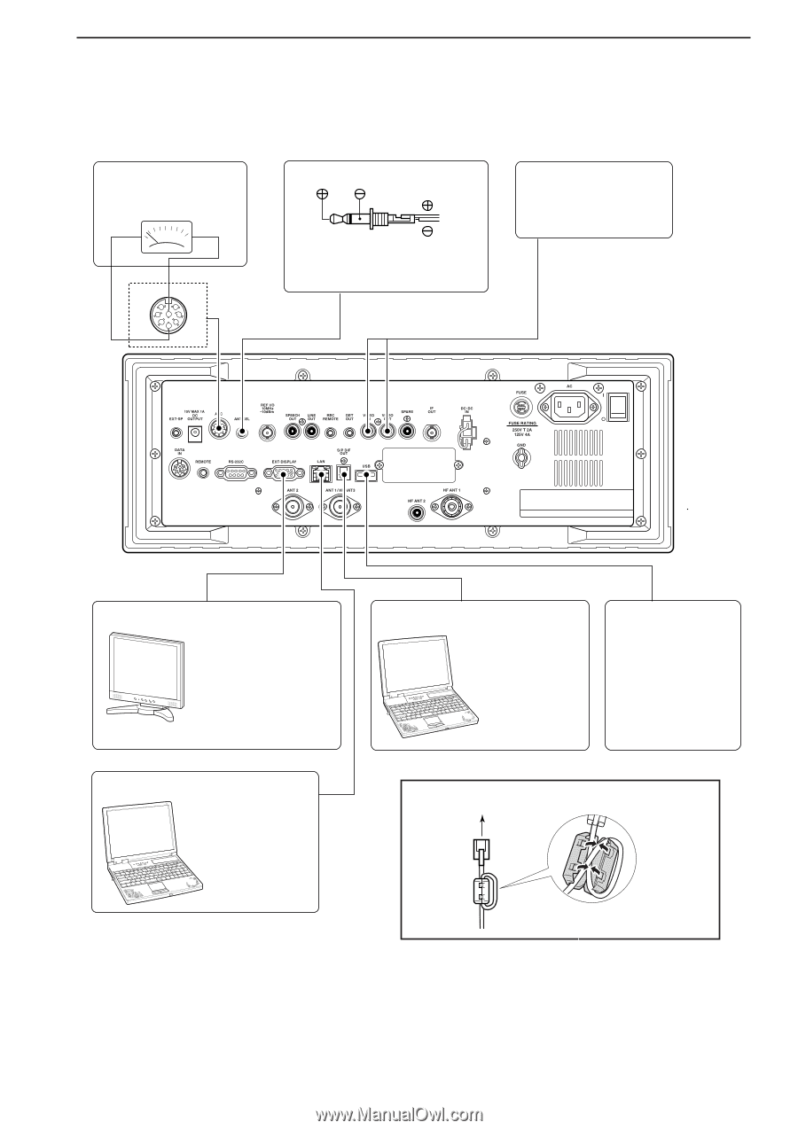
2 INSTALLATION AND CONNECTIONS D Rear panel-2 [METER] Connects an external meter, etc. Meter MOUT 76 381 54 2 GND [ACC] ANT SEL When the [ANT] switch is ON: 13.8 V DC output 100 mA max. Video equipment Connects a video recorder, etc. * No signals come out from [VIDEO OUT] for USA versions. External Display Connects a PC-style monitor display (at least 800×600 resolution). Video output signal can be turned ON and OFF in set mode (p. 11-9) [S/P DIF IN/OUT] Connects a PC for audio signal data (48 kHz, 16bit) output. [USB] Connects a USB equipment such as memory, hub or keyboard. Ethernet connector (p. 15-6) Connects a PC via a LAN for CPU firmware update. For Ferrite bead installation (example: LAN cable) LAN socket 2-7
-
 1
1 -
2
-
3
-
4
-
5
-
6
-
7
-
8
-
9
-
10
-
11
-
12
-
13
-
14
-
15
-
16
-
17
-
18
-
19
-
20
-
21
-
22
-
23
-
24
-
25
-
 26
26 -
 27
27 -
 28
28 -
 29
29 -
 30
30 -
 31
31 -
 32
32 -
 33
33 -
 34
34 -
 35
35 -
 36
36 -
37
-
38
-
39
-
40
-
41
-
42
-
43
-
44
-
45
-
46
-
47
-
48
-
49
-
50
-
51
-
52
-
53
-
54
-
55
-
56
-
57
-
58
-
59
-
60
-
61
-
62
-
63
-
64
-
65
-
66
-
67
-
68
-
69
-
70
-
71
-
72
-
73
-
74
-
75
-
76
-
77
-
78
-
79
-
80
-
81
-
82
-
83
-
84
-
85
-
86
-
87
-
88
-
89
-
90
-
91
-
92
-
93
-
94
-
95
-
96
-
97
-
98
-
99
-
100
-
101
-
102
-
103
-
104
-
105
-
106
-
107
-
108
-
109
-
110
-
111
-
112
-
113
-
114
-
115
-
116
-
117
-
118
-
119
-
120
-
121
-
122
-
123
-
124
-
125
-
126
-
127
-
128
-
129
-
130
-
131
-
132
-
133
-
134
-
135
-
136
-
137
-
138
-
139
-
140
-
141
-
142
-
143
-
144
-
145
-
146
-
147
-
148
-
149
-
150
-
151
-
152
-
153
-
154
-
155
-
156
-
157
-
158
-
159
-
160
-
161
-
162
-
163
-
164
-
165
-
166
-
167
-
168
-
169
-
170
-
171
-
172
-
173
-
174
-
175
-
176
-
177
-
178
-
179
-
180
-
181
-
182
-
183
-
184
-
185
-
186
-
187
-
188
-
189
-
190
-
191
-
192
-
193
-
194
 |
 |
2-7
2
INSTALLATION AND CONNECTIONS
D
Rear panel—2
For Ferrite bead installation
LAN
socket
(example: LAN cable)
1
2
3
4
5
6
7
8
External Display
Connects a PC-style
monitor display (at least
800
×
600 resolution).
Video output signal can
be turned ON and OFF
in set mode (p. 11-9)
Video equipment
Connects a video re-
corder, etc.
No signals come out from [VID-
EO OUT] for USA versions.
Connects a PC
for audio signal
data (48 kHz, 16-
bit) output.
Connects a USB
equipment such as
memory, hub or
keyboard.
[S/P DIF IN/OUT]
[USB]
Connects a PC
via a LAN for CPU
firmware update.
[METER]
Connects an external
meter, etc.
Meter
Ethernet connector
(p. 15-6)
MOUT
GND
[ACC]
ANT SEL
When the [ANT] switch is ON:
13.8 V DC output 100 mA max.
*