Icom IC-R9500 Instruction Manual - Page 27
Antenna connection
 |
View all Icom IC-R9500 manuals
Add to My Manuals
Save this manual to your list of manuals |
Page 27 highlights
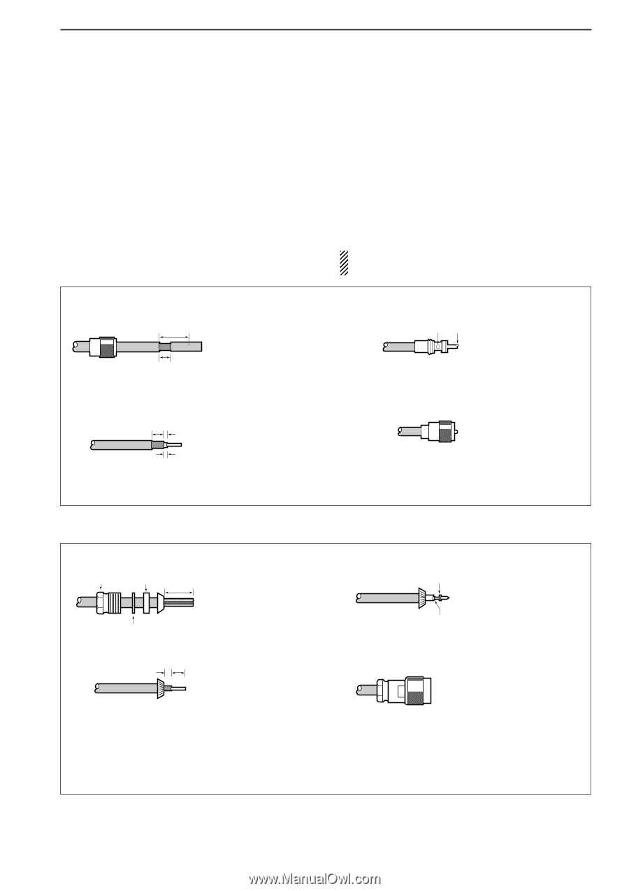
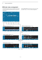
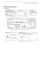
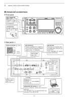
2 INSTALLATION AND CONNECTIONS ■ Antenna connection PL-259 CONNECTOR INSTALLATION EXAMPLE q Coupling ring 30 mm 10 mm (soft solder) Slide the coupling ring down. Strip the cable jacket and tin the braid. w Strip the cable as 10 mm Soft shown at left. Tin the solder centerr conductor. 1-2 mm Your antenna plays a very important role in receiver operation. If the antenna is poor, your receiver cannot give you the best performance. The IC-R9500 requires at least 2 antennas (ANT 1/HF ANT 3, ANT 2) for full coverage from 100 kHz to 3335 MHz. Select an antenna, such as a well matched 50 Ω antenna and feedline. When you wish to use a long wire antenna for short wave bands, use one as long as possible (at least 10 m, 32.8 ft). CAUTION: Protect your receiver from lightning by using a lightning arrestor. e solder solder Slide the connector body on and solder it. r Screw the coupling ring onto the connector body. 30 mm ≈ 9⁄8 in 10 mm ≈ 3⁄8 in 1-2 mm ≈ 1⁄16 in TYPE-N CONNECTOR INSTALLATION EXAMPLE q Nut Rubber gasket 15 mm Clamp Washer Slide the nut, washer, rubber gasket and clamp over the coaxial cable, then cut the end of the cable evenly. w 3 mm 6 mm Strip the cable and fold the braid back over the clamp. Center conductor e Solder hole Tin the center conductor. Install the center conductor pin and solder it. No space r Plug body Carefully slide the plug body into place aligning the center conductor pin on the cable. Tighten the nut onto the plug body. • Be sure the center pin is flush with the end of the plug body. 15 mm ≈ 19⁄32 in 6 mm ≈ 1⁄4 in 3 mm ≈ 1⁄8 in 2-3
-
 1
1 -
2
-
3
-
4
-
5
-
6
-
7
-
8
-
9
-
10
-
11
-
12
-
13
-
14
-
15
-
16
-
17
-
18
-
19
-
20
-
21
-
 22
22 -
 23
23 -
 24
24 -
 25
25 -
 26
26 -
 27
27 -
 28
28 -
 29
29 -
 30
30 -
 31
31 -
 32
32 -
33
-
34
-
35
-
36
-
37
-
38
-
39
-
40
-
41
-
42
-
43
-
44
-
45
-
46
-
47
-
48
-
49
-
50
-
51
-
52
-
53
-
54
-
55
-
56
-
57
-
58
-
59
-
60
-
61
-
62
-
63
-
64
-
65
-
66
-
67
-
68
-
69
-
70
-
71
-
72
-
73
-
74
-
75
-
76
-
77
-
78
-
79
-
80
-
81
-
82
-
83
-
84
-
85
-
86
-
87
-
88
-
89
-
90
-
91
-
92
-
93
-
94
-
95
-
96
-
97
-
98
-
99
-
100
-
101
-
102
-
103
-
104
-
105
-
106
-
107
-
108
-
109
-
110
-
111
-
112
-
113
-
114
-
115
-
116
-
117
-
118
-
119
-
120
-
121
-
122
-
123
-
124
-
125
-
126
-
127
-
128
-
129
-
130
-
131
-
132
-
133
-
134
-
135
-
136
-
137
-
138
-
139
-
140
-
141
-
142
-
143
-
144
-
145
-
146
-
147
-
148
-
149
-
150
-
151
-
152
-
153
-
154
-
155
-
156
-
157
-
158
-
159
-
160
-
161
-
162
-
163
-
164
-
165
-
166
-
167
-
168
-
169
-
170
-
171
-
172
-
173
-
174
-
175
-
176
-
177
-
178
-
179
-
180
-
181
-
182
-
183
-
184
-
185
-
186
-
187
-
188
-
189
-
190
-
191
-
192
-
193
-
194
 |
 |