Icom IC-R9500 Instruction Manual - Page 4
Supplied Accessories
 |
View all Icom IC-R9500 manuals
Add to My Manuals
Save this manual to your list of manuals |
Page 4 highlights
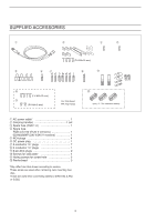
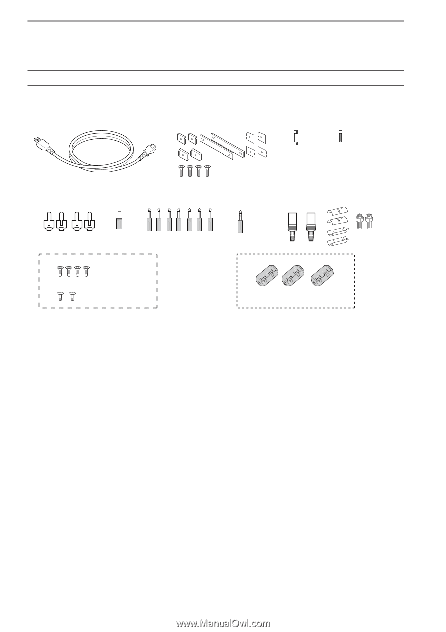
SUPPLIED ACCESSORIES q w e r (FH M4×16 mm) t y u i o !0 (FH M4×12 mm) !1 (PH M4×8 mm) FH: Flat head PH: Pan head q AC power cable 1 w Carrying handles 1 set e Spare fuse (FGB 1 A 1 r Spare fuse FGB 4 A (100 V/120 V versions 1 0234002MXP (230 V/240 V versions 1 t RCA plugs 4 y DC power plug 1 u 2-conductor 1⁄8″ plugs 7 i 3-conductor 1⁄8″ plugs 1 o 8 pin ACC plugs 2 !0 Screws for side plate 4 !1 Hiding screws for screw hole 2 !2 Ferrite bead 3 *May differ from that shown according to version. †These screw are used when removing rack mounting han- dles. ‡These are used when connecting cables to [DATA IN], [LAN] or [USB]. !2 (see p. 2-7 for installation details) iii
-
 1
1 -
 2
2 -
 3
3 -
 4
4 -
 5
5 -
 6
6 -
 7
7 -
 8
8 -
 9
9 -
 10
10 -
11
-
12
-
13
-
14
-
15
-
16
-
17
-
18
-
19
-
20
-
21
-
22
-
23
-
24
-
25
-
26
-
27
-
28
-
29
-
30
-
31
-
32
-
33
-
34
-
35
-
36
-
37
-
38
-
39
-
40
-
41
-
42
-
43
-
44
-
45
-
46
-
47
-
48
-
49
-
50
-
51
-
52
-
53
-
54
-
55
-
56
-
57
-
58
-
59
-
60
-
61
-
62
-
63
-
64
-
65
-
66
-
67
-
68
-
69
-
70
-
71
-
72
-
73
-
74
-
75
-
76
-
77
-
78
-
79
-
80
-
81
-
82
-
83
-
84
-
85
-
86
-
87
-
88
-
89
-
90
-
91
-
92
-
93
-
94
-
95
-
96
-
97
-
98
-
99
-
100
-
101
-
102
-
103
-
104
-
105
-
106
-
107
-
108
-
109
-
110
-
111
-
112
-
113
-
114
-
115
-
116
-
117
-
118
-
119
-
120
-
121
-
122
-
123
-
124
-
125
-
126
-
127
-
128
-
129
-
130
-
131
-
132
-
133
-
134
-
135
-
136
-
137
-
138
-
139
-
140
-
141
-
142
-
143
-
144
-
145
-
146
-
147
-
148
-
149
-
150
-
151
-
152
-
153
-
154
-
155
-
156
-
157
-
158
-
159
-
160
-
161
-
162
-
163
-
164
-
165
-
166
-
167
-
168
-
169
-
170
-
171
-
172
-
173
-
174
-
175
-
176
-
177
-
178
-
179
-
180
-
181
-
182
-
183
-
184
-
185
-
186
-
187
-
188
-
189
-
190
-
191
-
192
-
193
-
194
 |
 |
q
AC power cable*
………………………………… 1
w
Carrying handles ……………………………… 1 set
e
Spare fuse (FGB 1 A)
…………………………… 1
r
Spare fuse
FGB 4 A (100 V/120 V versions)
………………… 1
0234002MXP (230 V/240 V versions)
…………… 1
t
RCA plugs ………………………………………… 4
y
DC power plug
…………………………………… 1
u
2-conductor
1
/
8
″
plugs
…………………………… 7
i
3-conductor
1
/
8
″
plugs
…………………………… 1
o
8 pin ACC plugs …………………………………… 2
!
0
Screws for side plate
†
…………………………… 4
!
1
Hiding screws for screw hole
†
…………………… 2
!
2
Ferrite bead
‡
……………………………………… 3
*May differ from that shown according to version.
†
These screw are used when removing rack mounting han-
dles.
‡
These are used when connecting cables to [DATA IN], [LAN]
or [USB].
iii
SUPPLIED ACCESSORIES
q
o
!
0
!
1
t
y
u
i
e
w
r
(FH M4
×
16 mm)
(FH M4
×
12 mm)
(PH M4
×
8 mm)
PH: Pan head
FH: Flat head
!
2
(see p. 2-7 for installation details)