Icom IC-R9500 Instruction Manual - Page 15
Af Control [af], Bass Response Control [bass], Treble Response Control [treble], Multifunction
 |
View all Icom IC-R9500 manuals
Add to My Manuals
Save this manual to your list of manuals |
Page 15 highlights
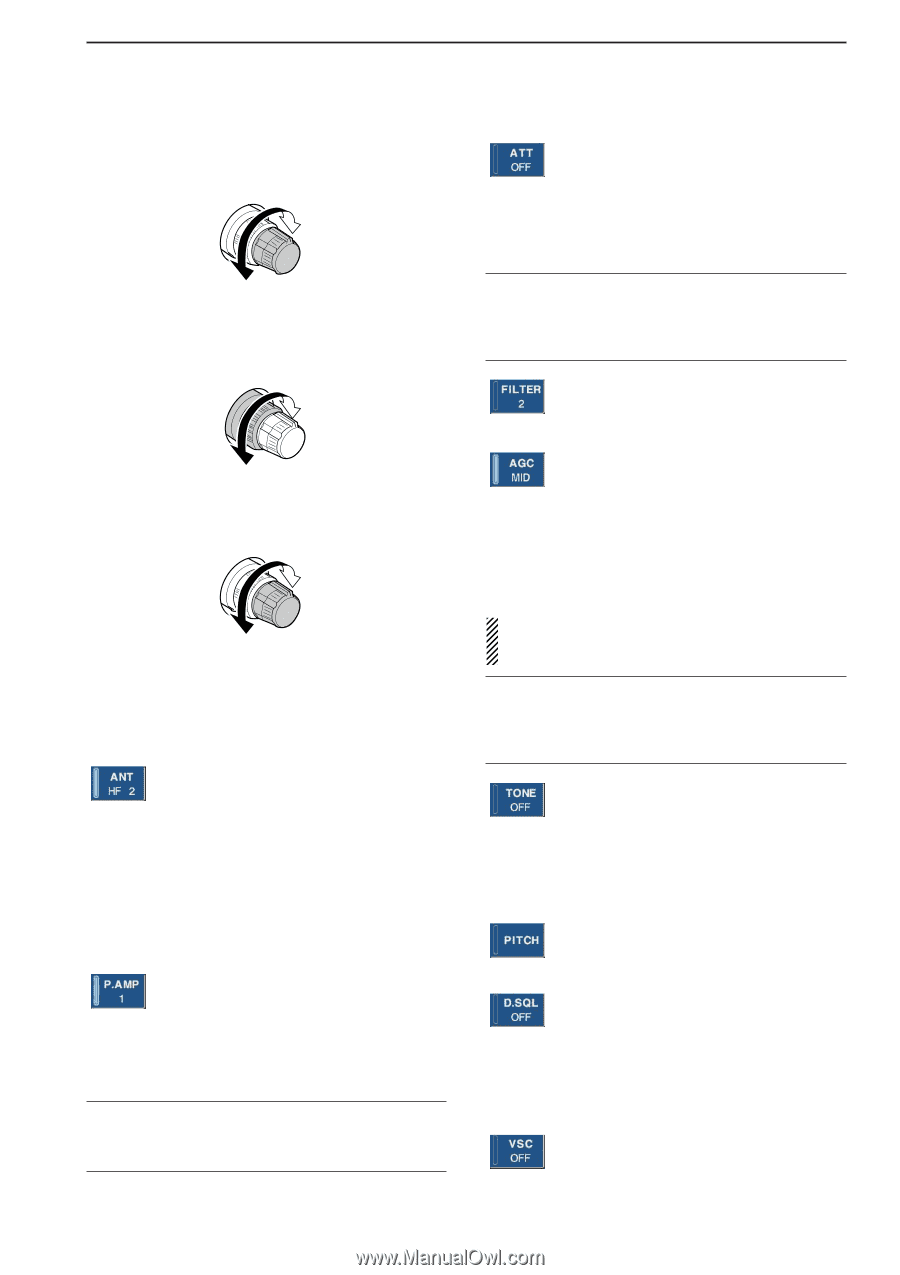
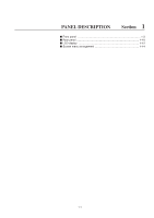
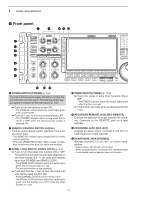
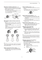
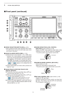
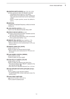
1 PANEL DESCRIPTION @2 AF CONTROL [AF] (inner control; p. 3-8) Varies the audio output level of the speaker or headphones. Audio output increases Audio output decreases @3 BASS RESPONSE CONTROL [BASS] (outer control; p. 3-9) Adjusts the bass response of the audio output. Bass level increases ➥ Selects the attenuator when pushed. (p. 5-9) • HF bands: 6, 12, 18, 24, 30 dB. • 30-1150 MHz: 10, 20, 30 dB. • 1150-3335 MHz: 20 dB only. ➥ Turns OFF the attenuator when pushed and held for 1 sec. (p. 5-9) ✔ What is the attenuator? The attenuator prevents a desired signal from distorting when very strong signals are near the receiving frequency, or when very strong electric fields, such as from a broadcasting station, are near your location. ➥ Selects one of 3 IF filter settings. ➥ Enters the filter set screen when pushed and held for 1 sec. Bass level decreases @4 TREBLE RESPONSE CONTROL [TREBLE] (inner control; p. 3-9) Adjusts the treble response of the audio output. Treble level increases Treble level decreases @5 MULTIFUNCTION SWITCHES Push to select the functions indicated in the LCD display to the right of these switches. • Functions vary depending on the operating condition. ➥ While operating HF bands, selects the antenna connector from HF ANT 1, HF ANT 2 and HF ANT 3 when pushed. (p. 9-3) • During 30-1150 MHz operation, only ANT 1 is available. • During 1150-3335 MHz operation, only ANT 2 is available. ➥ Turns the antenna control voltage ON and OFF form [ANT SEL] when pushed and held for 1 sec. (p. 9-3) ➥ Selects one of 2 receive RF preamps or bypasses them. (p. 5-9) ● HF bands • "P. AMP1" activates 10 dB preamp. • "P. AMP2" activates high-gain preamp. ● Above 30 MHz bands • Only "P. AMP" is available. ✔ What is the preamp? The preamp amplifies received signals in the front end circuit to improve S/N ratio and sensitivity. Select "P. AMP1" or "P. AMP2" when receiving weak signals. ➥ Activates and selects fast, middle or slow AGC time constant when pushed. (p. 5-10) • In FM, WFM or P25 mode, only "FAST" is available. • "VR (volume)" indicates that AGC time constant depends on [AGC] control. ➥ Enters the AGC set mode when pushed and held for 1 sec. (p. 5-10) AGC time constant can be set from 0.1 to 8.0 sec. (depends on mode), or turned OFF. When AGC is "OFF," the S-meter does not function. ✔ What is the AGC? The AGC controls receiver gain to produce a constant audio output level, even when the received signal strength varies dramatically. Select "FAST" for tuning and then select "MID" or "SLOW" depending on the receiving conditions. ➥ Switches between the tone squelch, DTCS squelch function and no-tone operation when pushed in FM mode. (p. 4-4) ➥ Enters the tone set mode when pushed and held for 1 sec. in FM, FSK mode. (pgs. 4-4, 4-12) ➥ Push to toggle the CW pitch setting screen ON and OFF in CW mode. (p.4-9) (Requires optional UT-122) ➥ Switches the digital squelch between NAC squelch, selective squelch and OFF in P25 mode. (p. 4-19) ➥ Enters the code set mode when pushed and held for 1 sec. in P25 mode. (p. 4-19) ➥ Push to switch the voice squelch control function ON and OFF; useful for scanning. (p. 8-3) 1-5
-
 1
1 -
2
-
3
-
4
-
5
-
6
-
7
-
8
-
9
-
 10
10 -
 11
11 -
 12
12 -
 13
13 -
 14
14 -
 15
15 -
 16
16 -
 17
17 -
 18
18 -
 19
19 -
 20
20 -
21
-
22
-
23
-
24
-
25
-
26
-
27
-
28
-
29
-
30
-
31
-
32
-
33
-
34
-
35
-
36
-
37
-
38
-
39
-
40
-
41
-
42
-
43
-
44
-
45
-
46
-
47
-
48
-
49
-
50
-
51
-
52
-
53
-
54
-
55
-
56
-
57
-
58
-
59
-
60
-
61
-
62
-
63
-
64
-
65
-
66
-
67
-
68
-
69
-
70
-
71
-
72
-
73
-
74
-
75
-
76
-
77
-
78
-
79
-
80
-
81
-
82
-
83
-
84
-
85
-
86
-
87
-
88
-
89
-
90
-
91
-
92
-
93
-
94
-
95
-
96
-
97
-
98
-
99
-
100
-
101
-
102
-
103
-
104
-
105
-
106
-
107
-
108
-
109
-
110
-
111
-
112
-
113
-
114
-
115
-
116
-
117
-
118
-
119
-
120
-
121
-
122
-
123
-
124
-
125
-
126
-
127
-
128
-
129
-
130
-
131
-
132
-
133
-
134
-
135
-
136
-
137
-
138
-
139
-
140
-
141
-
142
-
143
-
144
-
145
-
146
-
147
-
148
-
149
-
150
-
151
-
152
-
153
-
154
-
155
-
156
-
157
-
158
-
159
-
160
-
161
-
162
-
163
-
164
-
165
-
166
-
167
-
168
-
169
-
170
-
171
-
172
-
173
-
174
-
175
-
176
-
177
-
178
-
179
-
180
-
181
-
182
-
183
-
184
-
185
-
186
-
187
-
188
-
189
-
190
-
191
-
192
-
193
-
194
 |
 |