Icom IC-R9500 Instruction Manual - Page 156
Troubleshooting
 |
View all Icom IC-R9500 manuals
Add to My Manuals
Save this manual to your list of manuals |
Page 156 highlights
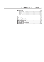
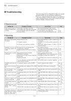
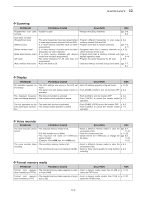
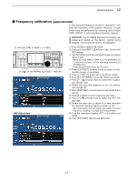
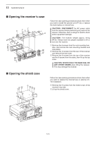
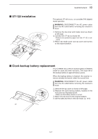
12 MAINTENANCE ■ Troubleshooting The following chart is designed to help you correct problems which are not equipment malfunctions. If you are unable to locate the cause of a problem or solve it through the use of this chart, contact you nearest Icom Dealer or Service Center. D Receiver power PROBLEM POSSIBLE CAUSE Power does not come on • Power cable is improperly connected. when the [POWER] switch • DC-DC power plug is improperly connected. is pushed. • The internal power supply is turned OFF. • The fuse is blown. SOLUTION • Re-connect the AC power cable correctly. • Re-connect the DC-DC power plug correctly. • Turn the internal power supply ON. • Check for the cause, then replace the fuse. REF. - - p. 3-2 p.12-8 D Receiving PROBLEM POSSIBLE CAUSE SOLUTION REF. No sounds come out from • Volume level is too low. the speaker. • The squelch is closed. • The RF gain is too decreases sensitivity. • Rotate [AF] clockwise to obtain a suitable lis- p. 3-8 tening level. • Turn [SQL] to 10 o'clock position to open the p. 3-8 squelch. • Rotate [RF GAIN] clockwise to obtain an p. 3-8 enough sensitivity. Sensitivity is too low, and • The antenna is not connected properly. only strong signals are • The attenuator is activated. audible. • A different antenna for HF band is selected. • Re-connect the antenna. - • Push [ATT] several times to select "ATT OFF." p. 5-9 • Push [ANT] several times to select the correct p. 9-3 antenna for the HF band. Received audio is unclear • Wrong operating mode is selected. • Select a suitable operating mode. p. 3-7 or distorted. • PBT function is activated. • Push [PBT CLR] for 1 sec. to reset the function. p. 5-11 • Noise blanker is turned ON when receiving a • Push [NB] to turn the noise blanker OFF. p. 5-15 strong signal. • Preamp is activated. • Push [P.AMP] once or twice to turn the function p. 5-9 OFF. • The noise reduction is activated and the [NR] • Set the [NR] control for maximum readability. p. 5-16 control is too far clockwise. The [ANT] switch does not • The selected frequency is above 30 MHz. function • Select a frequency below 30 MHz. pgs. 3-4, 9-3 [AFC] cannot be turned • The operating mode is not set in FM or WFM • Select FM or WFM mode to activate AFC. ON. mode. pgs. 3-7, 5-17 [AUTOTUNE](AFC) can- • The operating mode is set in FM, WFM, FSK • Select AM, SSB or CW mode to activate AUTO- pgs. 3-7, not be turned ON. or P25 mode. TUNE. 5-17 [VSC] cannot be turned • The operating mode is set in CW, FSK or P25 • Select FM, WFM, AM or SSB mode to activate pgs. 3-7, ON. mode. VSC. 8-3 [ANF] cannot be turned • The operating mode is set in CW, FSK or P25 • Select FM, WFM, AM or SSB mode to activate pgs. 3-7, ON. mode. ANF. 5-16 [ N O T C H 1 ] / [ N O T C H 2 ] • The operating mode is set in FM, WFM or P25 • Select AM, SSB, CW and FSK mode to activate pgs. 3-7, cannot be turned ON. mode. MN1/MN2. 5-16 The filter width cannot be • The operating mode is set in WFM or P25 • Select FM, AM, SSB, CW and FSK mode. changed. mode. pgs. 3-7, 5-12 A synthesized voice is not • "Speech Level" in the level set mode is too low • Set "Speech Level" to enough level in the set p. 11-6 emitted when pushing mode. [SPCH]. • "SPEECH Mix" in the others set mode is OFF. • Set "SPEECH Mix" to All or Operation in the set p. 11-11 mode. No sounds come out or • Either the audio tone controls is too decreas- • Rotate [BASS] or [TREBLE] clockwise to obtain p. 3-9 output level is too low from es position an enough audio output. [S/P DIF OUT], [ACC], [LINE OUT], [REC OUT]. 12-2
-
 1
1 -
2
-
3
-
4
-
5
-
6
-
7
-
8
-
9
-
10
-
11
-
12
-
13
-
14
-
15
-
16
-
17
-
18
-
19
-
20
-
21
-
22
-
23
-
24
-
25
-
26
-
27
-
28
-
29
-
30
-
31
-
32
-
33
-
34
-
35
-
36
-
37
-
38
-
39
-
40
-
41
-
42
-
43
-
44
-
45
-
46
-
47
-
48
-
49
-
50
-
51
-
52
-
53
-
54
-
55
-
56
-
57
-
58
-
59
-
60
-
61
-
62
-
63
-
64
-
65
-
66
-
67
-
68
-
69
-
70
-
71
-
72
-
73
-
74
-
75
-
76
-
77
-
78
-
79
-
80
-
81
-
82
-
83
-
84
-
85
-
86
-
87
-
88
-
89
-
90
-
91
-
92
-
93
-
94
-
95
-
96
-
97
-
98
-
99
-
100
-
101
-
102
-
103
-
104
-
105
-
106
-
107
-
108
-
109
-
110
-
111
-
112
-
113
-
114
-
115
-
116
-
117
-
118
-
119
-
120
-
121
-
122
-
123
-
124
-
125
-
126
-
127
-
128
-
129
-
130
-
131
-
132
-
133
-
134
-
135
-
136
-
137
-
138
-
139
-
140
-
141
-
142
-
143
-
144
-
145
-
146
-
147
-
148
-
149
-
150
-
 151
151 -
 152
152 -
 153
153 -
 154
154 -
 155
155 -
 156
156 -
 157
157 -
 158
158 -
 159
159 -
 160
160 -
 161
161 -
162
-
163
-
164
-
165
-
166
-
167
-
168
-
169
-
170
-
171
-
172
-
173
-
174
-
175
-
176
-
177
-
178
-
179
-
180
-
181
-
182
-
183
-
184
-
185
-
186
-
187
-
188
-
189
-
190
-
191
-
192
-
193
-
194
 |
 |