Icom IC-R9500 Instruction Manual - Page 167
Command table - 06
 |
View all Icom IC-R9500 manuals
Add to My Manuals
Save this manual to your list of manuals |
Page 167 highlights
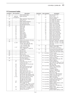
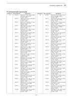
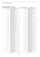
CONTROL COMMAND 13 D Command table Command 00 01 02 03 04 05 06 07 08 09 0A 0B 0C 0D 0E Sub command Description - Send frequency data Same as Send mode data command 06 - Read upper/lower frequencies for selected band - Read operating frequency - Read operating mode - Set operating frequency 00 Select LSB 01 Select USB 02 Select AM 03 Select CW 04 Select FSK 05 Select FM 07 Select CW-R 08 Select FSK-R 11 Select S-AM(D) 14 Select S-AM(L) 15 Select S-AM(U) 16 Select P25 - Select (Last selected) VFO mode - 0-1219* 0-12* Select memory mode Select memory channel *0-999, 1000-1099 (A00-A99), 1100-1199 (S00-S99), 1200-1219 (P0A-P9A) Select memory bank *0-9, 10 (Bank-A), 11 (Bank-S), 12 (Bank-P) - Memory write - Memory to VFO - Memory clear - Read offset frequency (see p. 13-10 for details) - Set offset frequency (see p. 13-10 for details) 00 01 02 03 04 12 13 22 23 24 42 A0 AA A1-A7 B0 B1 B2 D0 Scan stop Programmed scan (Prog 0)/ memory scan start Programmed scan (Prog 0) start ∂F scan start Auto memory write scan start Fine programmed scan start Fine ∂F scan start Memory scan start Select memory scan start Mode select memory scan start Priority scan (Prio 0) start Set ∂F scan Fixed frequency ON Set ∂F scan Fixed frequency OFF Set ∂F scan span (A1=±5 kHz; A2=±10 kHz; A3=±20 kHz; A4=±50 kHz; A5=±100 kHz; A6=±500 kHz; A7=±1 MHz) Set as non-select channel Set as select channel (1-9=★(SEL)1-9; when no data command is specified, the previously set number or "★1" is selected) Set the number for select memory scan (0=ALL; 1-9=★(SEL)1-9 Set scan resume OFF Command 0E 10 11 12 13 14 Sub command Description D1 Set scan resume ON (Close Timer) D3 Set scan resume ON (Close and Delay) 10 Turn duplex OFF. (Simplex) 11 Turn duplex ON. (DUP-) 12 Turn duplex ON. (DUP+) 00 Select 1 Hz tuning step 01 Select 10 Hz tuning step 02 Select 100 Hz tuning step 03 Select 1 kHz tuning step 04 Select 2.5 kHz tuning step 05 Select 5 kHz tuning step 06 Select 6.25 kHz tuning step 07 Select 9 kHz tuning step 08 Select 10 kHz tuning step 09 Select 12.5 kHz tuning step 10 Select 20 kHz tuning step 11 Select 25 kHz tuning step 12 Select 100 kHz tuning step 13 Select 1 MHz tuning step 14 Select Prog tuning step - Select/read attenuator (00=OFF; 06=6 dB; 10=10 dB; 12=12 dB; 18=18 dB; 20=20 dB; 24=24 dB; 30=30 dB) 00 Select/read the antenna below 01 30 MHz. (00=HF ANT1, 02 01=HF ANT2, 02=HF ANT3) 00 Announce with voice synthesizer 01 (00=all data; 01=frequency and 02 S-meter level; 02=receive mode) 01 + Level data 02 + Level data 03 + Level data 06 + Level data 07 + Level data 08 + Level data 09 + Level data 0D + Level data 11 + Level data 12 + Level data 18 + Level data 19 + Level data 1A + Level data 1B + Level data 1C + Level data [AF] level setting (0=max. CCW to 255=max. CW) [RF] level setting (0=max. CCW to 255=11 o'clock) [SQL] level setting (0=11 o'clock to 255=max. CW) [NR] level setting (0=min. to 255=max.) Left [TWIN PBT] setting or IF shift setting (0=max. CCW, 128=center, 255=max. CW) Right [TWIN PBT] setting (0=max. CCW, 128=center, 255=max. CW) [CW PITCH] setting (0=300 Hz, 128=600 Hz, 255=900 Hz; 5 Hz steps) [NOTCH1] setting (0=low freq. to 255=high freq.) [AGC] control setting (0=max. CCW to 255=max. CW) [NB] control setting (0=max. CCW to 255=max. CW) [CONTRAST] setting (0=max. CCW to 255=max. CW) [BRIGHT] setting (0=max. CCW to 255=max. CW) [NOTCH2] setting (0=low freq. to 255=high freq.) [BASS] setting (0=max. CCW to 255=max. CW) [TREBLE] setting (0=max. CCW to 255=max. CW) 13-3
-
 1
1 -
2
-
3
-
4
-
5
-
6
-
7
-
8
-
9
-
10
-
11
-
12
-
13
-
14
-
15
-
16
-
17
-
18
-
19
-
20
-
21
-
22
-
23
-
24
-
25
-
26
-
27
-
28
-
29
-
30
-
31
-
32
-
33
-
34
-
35
-
36
-
37
-
38
-
39
-
40
-
41
-
42
-
43
-
44
-
45
-
46
-
47
-
48
-
49
-
50
-
51
-
52
-
53
-
54
-
55
-
56
-
57
-
58
-
59
-
60
-
61
-
62
-
63
-
64
-
65
-
66
-
67
-
68
-
69
-
70
-
71
-
72
-
73
-
74
-
75
-
76
-
77
-
78
-
79
-
80
-
81
-
82
-
83
-
84
-
85
-
86
-
87
-
88
-
89
-
90
-
91
-
92
-
93
-
94
-
95
-
96
-
97
-
98
-
99
-
100
-
101
-
102
-
103
-
104
-
105
-
106
-
107
-
108
-
109
-
110
-
111
-
112
-
113
-
114
-
115
-
116
-
117
-
118
-
119
-
120
-
121
-
122
-
123
-
124
-
125
-
126
-
127
-
128
-
129
-
130
-
131
-
132
-
133
-
134
-
135
-
136
-
137
-
138
-
139
-
140
-
141
-
142
-
143
-
144
-
145
-
146
-
147
-
148
-
149
-
150
-
151
-
152
-
153
-
154
-
155
-
156
-
157
-
158
-
159
-
160
-
161
-
 162
162 -
 163
163 -
 164
164 -
 165
165 -
 166
166 -
 167
167 -
 168
168 -
 169
169 -
 170
170 -
 171
171 -
 172
172 -
173
-
174
-
175
-
176
-
177
-
178
-
179
-
180
-
181
-
182
-
183
-
184
-
185
-
186
-
187
-
188
-
189
-
190
-
191
-
192
-
193
-
194
 |
 |