Icom IC-R9500 Instruction Manual - Page 13
Panel Description
 |
View all Icom IC-R9500 manuals
Add to My Manuals
Save this manual to your list of manuals |
Page 13 highlights
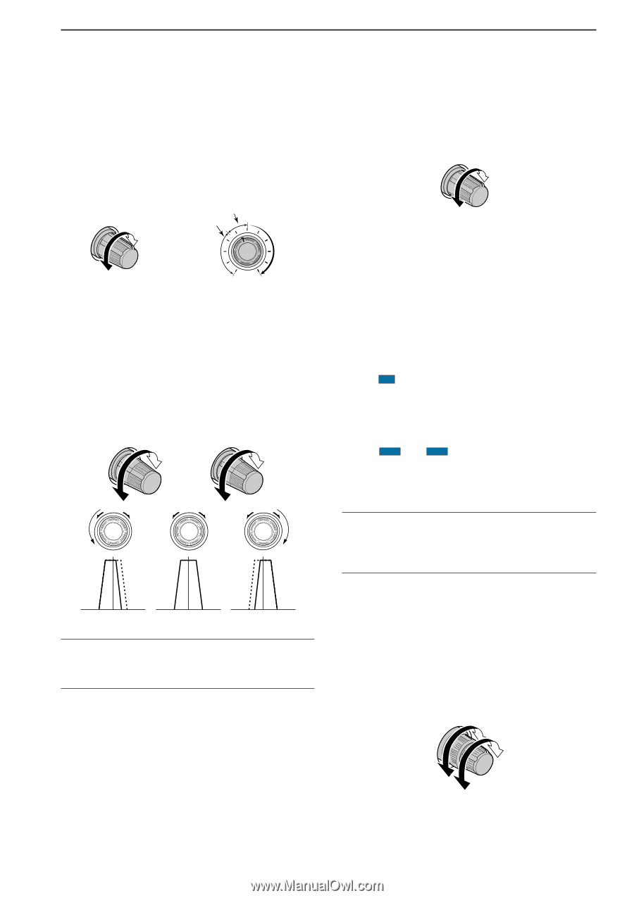
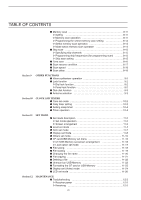
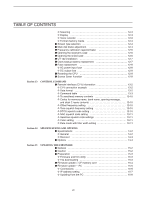
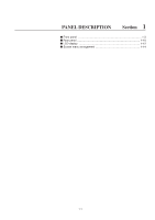
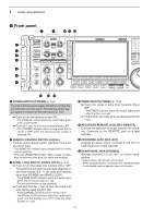
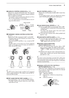
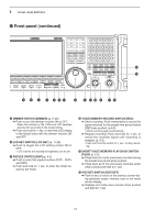
1 PANEL DESCRIPTION i SQUELCH CONTROL [SQUELCH] (p. 3-8) Adjusts the squelch threshold level. The squelch disables output from the speaker (closed condition) when no signal is received. • The squelch control is particularly effective for FM or AM. It is also available for other modes. • 11 to 12 o'clock position is recommended for any setting of the [SQL] control. Shallow Deep Noise squelch Squelch threshold Squelch is open. S-meter squelch Shallow Deep o PASSBAND TUNING CONTROLS [TWIN PBT] (p. 5-11) Adjusts the IF filter "passband width" via the DSP. • Passband width and shift frequency are shown on the multifunction display. • Push and hold [PBT CLEAR] for 1 sec. to clear the PBT settings. • Variable range is set to half of the IF filter passband width. 25 Hz steps and 50 Hz steps are available in SSB, CW and FSK modes. (PBT1) (PBT2) - + !1 AGC CONTROL [AGC] (p. 5-10) Adjusts the continuously-variable AGC circuit time constant. • To use [AGC] control, push the appropriate band's [AGC VR/OFF] ([AGC VR] indicator lights green). Slow Fast !2 AGC SWITCH [AGC VR/OFF] (p. 5-10) ➥ Push to toggle [AGC] control usage ON or OFF. • Use [AGC] control to set the AGC time constant when switched ON. • The [AGC VR] indicator above this switch lights green when the control is ON. ➥ Turns the AGC function OFF when pushed and held for 1 sec. !3 AUTO NOTCH SWITCH [ANF] (p. 5-16) ➥ Turns the auto notch function ON or OFF when pushed in SSB, AM, FM and WFM mode. • " AN " appears when auto notch is in use. !4 MANUAL NOTCH SWITCHES [NOTCH1]/[NOTCH2] (p. 5-16) ➥ Turns the manual notch function ON or OFF when pushed in SSB, CW, AM and FSK mode. • " MN1 " or " MN2 " appear when manual notch is in use. ➥ Switches the manual notch characteristics between wide, middle and narrow when pushed and held for 1 sec. ✔ What is the notch function? The notch function eliminates unwanted CW or AM carrier tones while preserving the desired voice signal. The DSP circuit automatically adjusts the notch frequency to effectively eliminate unwanted tones. High cut Center Low cut ✔ What is the PBT control? The PBT function electronically modifies the IF passband width to reject interference. This receiver uses the DSP circuit for the PBT function. !0 PBT CLEAR SWITCH [PBT CLEAR] (p. 5-11) Push and hold for 1 sec. to clear the PBT settings. • The [PBT CLEAR] indicator above this switch lights when PBT is in use. !5 MANUAL NOTCH FILTER CONTROLS [NOTCH1]/[NOTCH2] (p. 5-16) Varies the "notch" frequency of the manual notch filter to reject an interfering signal while the manual notch function is ON. • Notch filter center frequency: SSB : -1060 Hz to 4040 Hz CW : CW pitch freq. + 2540 Hz to CW pitch freq. -2540 Hz AM : -5100 Hz to 5100 Hz NOTCH1 NOTCH2 Lower frequency Higher frequency 1-3
-
 1
1 -
2
-
3
-
4
-
5
-
6
-
7
-
 8
8 -
 9
9 -
 10
10 -
 11
11 -
 12
12 -
 13
13 -
 14
14 -
 15
15 -
 16
16 -
 17
17 -
 18
18 -
19
-
20
-
21
-
22
-
23
-
24
-
25
-
26
-
27
-
28
-
29
-
30
-
31
-
32
-
33
-
34
-
35
-
36
-
37
-
38
-
39
-
40
-
41
-
42
-
43
-
44
-
45
-
46
-
47
-
48
-
49
-
50
-
51
-
52
-
53
-
54
-
55
-
56
-
57
-
58
-
59
-
60
-
61
-
62
-
63
-
64
-
65
-
66
-
67
-
68
-
69
-
70
-
71
-
72
-
73
-
74
-
75
-
76
-
77
-
78
-
79
-
80
-
81
-
82
-
83
-
84
-
85
-
86
-
87
-
88
-
89
-
90
-
91
-
92
-
93
-
94
-
95
-
96
-
97
-
98
-
99
-
100
-
101
-
102
-
103
-
104
-
105
-
106
-
107
-
108
-
109
-
110
-
111
-
112
-
113
-
114
-
115
-
116
-
117
-
118
-
119
-
120
-
121
-
122
-
123
-
124
-
125
-
126
-
127
-
128
-
129
-
130
-
131
-
132
-
133
-
134
-
135
-
136
-
137
-
138
-
139
-
140
-
141
-
142
-
143
-
144
-
145
-
146
-
147
-
148
-
149
-
150
-
151
-
152
-
153
-
154
-
155
-
156
-
157
-
158
-
159
-
160
-
161
-
162
-
163
-
164
-
165
-
166
-
167
-
168
-
169
-
170
-
171
-
172
-
173
-
174
-
175
-
176
-
177
-
178
-
179
-
180
-
181
-
182
-
183
-
184
-
185
-
186
-
187
-
188
-
189
-
190
-
191
-
192
-
193
-
194
 |
 |