Icom IC-R9500 Instruction Manual - Page 34
Transceive function, Monitor display connection
 |
View all Icom IC-R9500 manuals
Add to My Manuals
Save this manual to your list of manuals |
Page 34 highlights
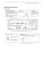
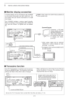
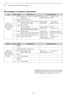
2 INSTALLATION AND CONNECTIONS ■ Monitor display connection A monitor display can be connected to the IC-R9500 via the [DATA IN] socket and [EXT-DISPLAY]. You can monitor the LCD monitor information on a large size display. The IC-R9500 includes a picture signal decoder. When connecting a TV set equipped with a VIDEO IN jack, you can monitor TV signals such as amateur TV. [EXT-DISPLAY] NOTE: Video output from [DATA IN] is available an NTSC system only. External Display Connects a PC-style monitor display (at least 800×600 resolution). Video output signal can be turned ON and OFF in display set mode. (p. 11-9) VIDEO 7 6 381 54 2 GND [DATA IN] *1LCD output including TV signal *2TV signal only [VIDEO OUT] *1 Video output signal can be selected 'VIDEO IN' or 'LCD' in display set (Video) mode. (p. 11-25) *2 No signals come out from [VIDEO OUT] for USA versions. TV set [VIDEO IN] or ■ Transceive function Icom CI-V transceivers or receivers can be connected via the [REMOTE] jack. The frequency and mode settings will follow* when either radio is changed. [ACC] Pin 3 * When a set frequency is out-of-range for one of the connected transceivers or receivers, the connected radio's frequency/mode does not change. Connect [ACC] socket when the ICR9500 is connected with transceiver. This connection mutes the IC-R9500 when transceiver transmits. Connect to [REMOTE] jack • Be sure the "CI-V Transceive" item is turned ON in the others set mode (p. 11-14). 2-10
-
 1
1 -
2
-
3
-
4
-
5
-
6
-
7
-
8
-
9
-
10
-
11
-
12
-
13
-
14
-
15
-
16
-
17
-
18
-
19
-
20
-
21
-
22
-
23
-
24
-
25
-
26
-
27
-
28
-
 29
29 -
 30
30 -
 31
31 -
 32
32 -
 33
33 -
 34
34 -
 35
35 -
 36
36 -
 37
37 -
 38
38 -
 39
39 -
40
-
41
-
42
-
43
-
44
-
45
-
46
-
47
-
48
-
49
-
50
-
51
-
52
-
53
-
54
-
55
-
56
-
57
-
58
-
59
-
60
-
61
-
62
-
63
-
64
-
65
-
66
-
67
-
68
-
69
-
70
-
71
-
72
-
73
-
74
-
75
-
76
-
77
-
78
-
79
-
80
-
81
-
82
-
83
-
84
-
85
-
86
-
87
-
88
-
89
-
90
-
91
-
92
-
93
-
94
-
95
-
96
-
97
-
98
-
99
-
100
-
101
-
102
-
103
-
104
-
105
-
106
-
107
-
108
-
109
-
110
-
111
-
112
-
113
-
114
-
115
-
116
-
117
-
118
-
119
-
120
-
121
-
122
-
123
-
124
-
125
-
126
-
127
-
128
-
129
-
130
-
131
-
132
-
133
-
134
-
135
-
136
-
137
-
138
-
139
-
140
-
141
-
142
-
143
-
144
-
145
-
146
-
147
-
148
-
149
-
150
-
151
-
152
-
153
-
154
-
155
-
156
-
157
-
158
-
159
-
160
-
161
-
162
-
163
-
164
-
165
-
166
-
167
-
168
-
169
-
170
-
171
-
172
-
173
-
174
-
175
-
176
-
177
-
178
-
179
-
180
-
181
-
182
-
183
-
184
-
185
-
186
-
187
-
188
-
189
-
190
-
191
-
192
-
193
-
194
 |
 |
