Icom IC-R9500 Instruction Manual - Page 20
Rear panel
 |
View all Icom IC-R9500 manuals
Add to My Manuals
Save this manual to your list of manuals |
Page 20 highlights
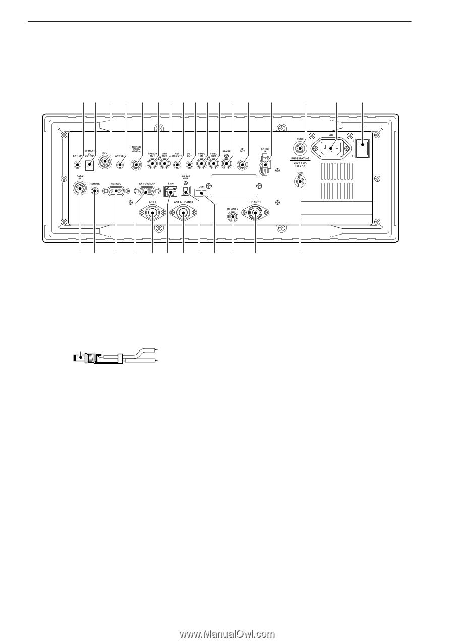
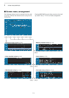
1 PANEL DESCRIPTION ■ Rear panel q w e r t y u i o !0 !1 !2 !3 !4 !5 !6 !7 @9 @8 @7 @6 @5 @4 @3 @2 @1 @0 !9 !8 q EXTERNAL SPEAKER JACK [EXT-SP] (p. 2-6) Connects an external speaker (4-8 Ω), if desired. w DC OUTPUT JACK [DC OUTPUT] (p. 2-6) Outputs regulated 15 V DC (approx.) for external equipment. Connected in parallel with 13.8 V outputs of [ACC]. (max. 1 A total) _ + _ e ACCESSORY SOCKET [ACC] (p. 2-6) Enables connection of external equipment such as an automatic antenna selector, a TNC for data communications, etc. • See p. 2-12 for socket information. r ANTENNA SELECTOR VOLTAGE OUTPUT JACK [ANT SEL] Outputs regulated 13.8 V DC (max. 100 mA) for external preamplifier or antenna selector, etc. t REFERENCE SIGNAL INPUT/OUTPUT TERMINAL [REF I/O 10MHz-10dBm] Inputs/outputs a 10 MHz reference signal. y SPEECH OUTPUT JACK [SPEECH OUT] (p. 2-9) Outputs an operating frequency, mode, S-meter indication and time with a synthesized voice when pushing [SPCH] or scan stopped. • Turn ON the "REC SPCH" in the others set mode to activate this jack when scan stopped. (p. 11-11) • Output level can be adjusted in ACC set mode. (p. 11-7) u LINE OUTPUT JACK [LINE OUT] Audio output jack for tape recorder. The fixed audio output level is set for a tape recorder AUX jack. i RECORDER REMOTE JACK [REC REMOTE] Controls the operation of a tape recorder for recording. Connects to the REMOTE jack on a tape recorder. o DETECTOR OUTPUT JACK [DET OUT] Outputs the detector output signal. !0 VIDEO INPUT JACK [VIDEO IN] Accepts video signals for display on the LCD monitor when the [DISPLAY] switch is ON. !1 VIDEO OUTPUT JACK [VIDEO OUT] Outputs video signals when TV frequencies with WFM mode are received. The NTSC M, PAL B/G, PAL I, PAL D and SECAM K system can be accepted. (No signals come out for USA versions.) !2 SPARE JACK [SPARE] (p. 2-3) No connection. !3 IF OUTPUT JACK [IF OUT] (p. 2-3) Outputs a 10.7 MHz IF signal. Output level is the same level as an antenna input signal or below (when the AGC function is activated or attenuator is ON.) !4 DC-DC POWER SOCKET [DC-DC IN] (p. 2-6) Accepts a regulated 13.5 to 15 V DC input. This socket does not accept voltage from a non-regulated power source such as a vehicle's battery. 1-10
-
 1
1 -
2
-
3
-
4
-
5
-
6
-
7
-
8
-
9
-
10
-
11
-
12
-
13
-
14
-
 15
15 -
 16
16 -
 17
17 -
 18
18 -
 19
19 -
 20
20 -
 21
21 -
 22
22 -
 23
23 -
 24
24 -
 25
25 -
26
-
27
-
28
-
29
-
30
-
31
-
32
-
33
-
34
-
35
-
36
-
37
-
38
-
39
-
40
-
41
-
42
-
43
-
44
-
45
-
46
-
47
-
48
-
49
-
50
-
51
-
52
-
53
-
54
-
55
-
56
-
57
-
58
-
59
-
60
-
61
-
62
-
63
-
64
-
65
-
66
-
67
-
68
-
69
-
70
-
71
-
72
-
73
-
74
-
75
-
76
-
77
-
78
-
79
-
80
-
81
-
82
-
83
-
84
-
85
-
86
-
87
-
88
-
89
-
90
-
91
-
92
-
93
-
94
-
95
-
96
-
97
-
98
-
99
-
100
-
101
-
102
-
103
-
104
-
105
-
106
-
107
-
108
-
109
-
110
-
111
-
112
-
113
-
114
-
115
-
116
-
117
-
118
-
119
-
120
-
121
-
122
-
123
-
124
-
125
-
126
-
127
-
128
-
129
-
130
-
131
-
132
-
133
-
134
-
135
-
136
-
137
-
138
-
139
-
140
-
141
-
142
-
143
-
144
-
145
-
146
-
147
-
148
-
149
-
150
-
151
-
152
-
153
-
154
-
155
-
156
-
157
-
158
-
159
-
160
-
161
-
162
-
163
-
164
-
165
-
166
-
167
-
168
-
169
-
170
-
171
-
172
-
173
-
174
-
175
-
176
-
177
-
178
-
179
-
180
-
181
-
182
-
183
-
184
-
185
-
186
-
187
-
188
-
189
-
190
-
191
-
192
-
193
-
194
 |
 |