Icom IC-R9500 Instruction Manual - Page 23
Tone/dtcs/nac/selective Squelch
 |
View all Icom IC-R9500 manuals
Add to My Manuals
Save this manual to your list of manuals |
Page 23 highlights
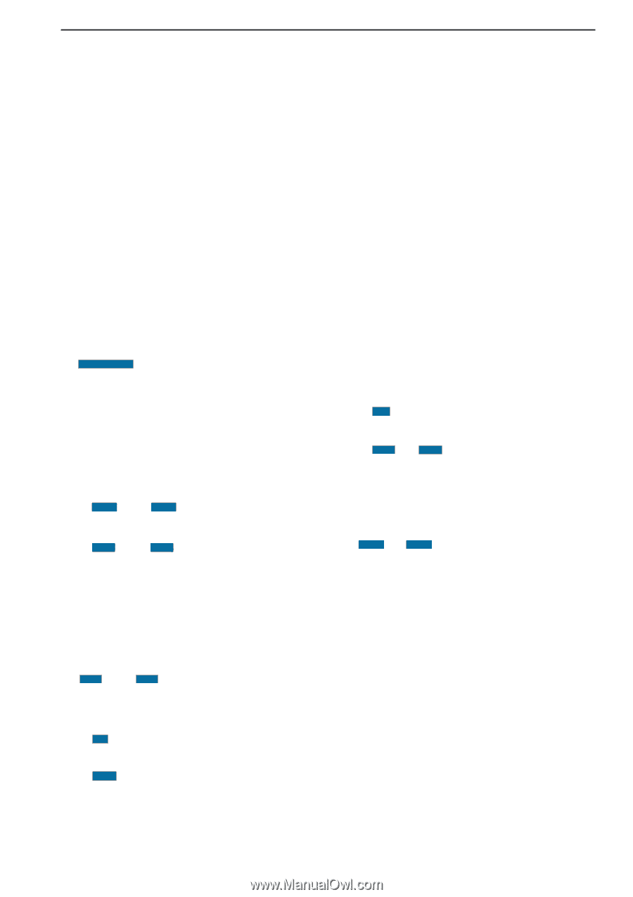
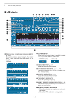
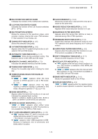
1 PANEL DESCRIPTION o MULTIFUNCTION SWITCH GUIDE Indicates the function of the multifunction switches. !0 LCD FUNCTION SWITCH GUIDE Indicates the function of the LCD function switches ([F-1] - [F-7]). !1 MULTIFUNCTION SCREEN Shows the screens for the spectrum scope, voice recorder, memory channel list, scan, FSK decoder, IF filter selection or set modes, etc. !2 TUNING STEP INDICATOR (p. 3-5) Shows the selected tuning step. !3 1/4 FUNCTION INDICATOR (p. 3-6) Appears when the 1/4-speed tuning function is activated in CW and FSK modes. !4 AUTOMATIC TUNE INDICATOR (p. 5-17) " AUTO TUNE " blinks during automatic tuning. This feature is active in AM, SSB and CW mode. !5 MEMORY CHANNEL INDICATOR (p. 7-3) Indicates the selected memory channel number. !6 TUNING DIGIT INDICATOR (p. 3-5) Shows the tuneable digit when rotating the main dial. !7 TONE/DTCS/NAC/SELECTIVE SQUELCH INDICATOR ➥ " TSQL " or " DTCS " appears when the tone squelch or DTCS squelch is set in FM mode. (p. 4-4) ➥ " NAC " or " SEL " appears when the NAC squelch or selective squelch is selected in P25 mode. (Requires optional UT-122.) (p.4-19) !8 BANK INDICATOR (p. 7-3) Appears when the bank limit function is in use and indicates the selected bank number. • BANK-0 to BANK-9, BANK-A (AUTO MW), BANK-S (SKIP) and BANK-P (SCAN EDGE) are selectable. !9 NOISE BLANKER INDICATOR (p. 5-15) " NB1 " or " NB2 " appears when either noise blanker 1 or noise blanker 2 is ON. This function is not available for FM, WFM or P25 mode. @0 CF CARD/USB-MEMORY INDICATOR (p. 11-16) ➥ " CF " appears when CF card is correctly connected and blinks while CF card is active. • This indicator is normally stayed ON. ➥ " USB " appears when USB equipment (USBMemory or keyboard, etc) is connected, and blinks while it is active. @1 CLOCK READOUT (p. 10-2) Shows the current time. Local and UTC time can indicate at the same time. @2 NOISE REDUCTION INDICATOR (p. 5-16) Appears when noise reduction function is in use. @3 BANDPASS FILTER INDICATOR Appears when the narrow filter (500 Hz or less) is selected during CW or FSK operation. @4 PASSBAND WIDTH INDICATOR (p. 5-11) Graphically displays the passband width for twin PBT operation and center frequency for IF shift operation. @5 AUDIO PEAK FILTER INDICATOR (p. 4-9) Appears when the audio peak filter function is in use. This function is available in CW mode @6 SHIFT FREQUENCY INDICATOR (p. 5-11) Shows the shift frequency of the IF filter. @7 NOTCH FILTER INDICATOR (p. 5-16) ➥ " AN " appears when the auto notch function is in use. This function is available in FM, WFM, AM and SSB modes. ➥ " MN1 " or " MN2 " appears when the manual notch filter function is in use. This function is available in AM, SSB, CW and FSK mode. @8 BAND WIDTH INDICATOR (p. 5-11) Shows the passband width of the IF filter. @9 DUPLEX INDICATOR (p. 4-3) " DUP- " or " DUP+ " appears when the negative duplex or positive duplex operation is selected, respectively. 1-13
-
 1
1 -
2
-
3
-
4
-
5
-
6
-
7
-
8
-
9
-
10
-
11
-
12
-
13
-
14
-
15
-
16
-
17
-
 18
18 -
 19
19 -
 20
20 -
 21
21 -
 22
22 -
 23
23 -
 24
24 -
 25
25 -
 26
26 -
 27
27 -
 28
28 -
29
-
30
-
31
-
32
-
33
-
34
-
35
-
36
-
37
-
38
-
39
-
40
-
41
-
42
-
43
-
44
-
45
-
46
-
47
-
48
-
49
-
50
-
51
-
52
-
53
-
54
-
55
-
56
-
57
-
58
-
59
-
60
-
61
-
62
-
63
-
64
-
65
-
66
-
67
-
68
-
69
-
70
-
71
-
72
-
73
-
74
-
75
-
76
-
77
-
78
-
79
-
80
-
81
-
82
-
83
-
84
-
85
-
86
-
87
-
88
-
89
-
90
-
91
-
92
-
93
-
94
-
95
-
96
-
97
-
98
-
99
-
100
-
101
-
102
-
103
-
104
-
105
-
106
-
107
-
108
-
109
-
110
-
111
-
112
-
113
-
114
-
115
-
116
-
117
-
118
-
119
-
120
-
121
-
122
-
123
-
124
-
125
-
126
-
127
-
128
-
129
-
130
-
131
-
132
-
133
-
134
-
135
-
136
-
137
-
138
-
139
-
140
-
141
-
142
-
143
-
144
-
145
-
146
-
147
-
148
-
149
-
150
-
151
-
152
-
153
-
154
-
155
-
156
-
157
-
158
-
159
-
160
-
161
-
162
-
163
-
164
-
165
-
166
-
167
-
168
-
169
-
170
-
171
-
172
-
173
-
174
-
175
-
176
-
177
-
178
-
179
-
180
-
181
-
182
-
183
-
184
-
185
-
186
-
187
-
188
-
189
-
190
-
191
-
192
-
193
-
194
 |
 |