Icom IC-R9500 Instruction Manual - Page 77
Twin PBT operation
 |
View all Icom IC-R9500 manuals
Add to My Manuals
Save this manual to your list of manuals |
Page 77 highlights
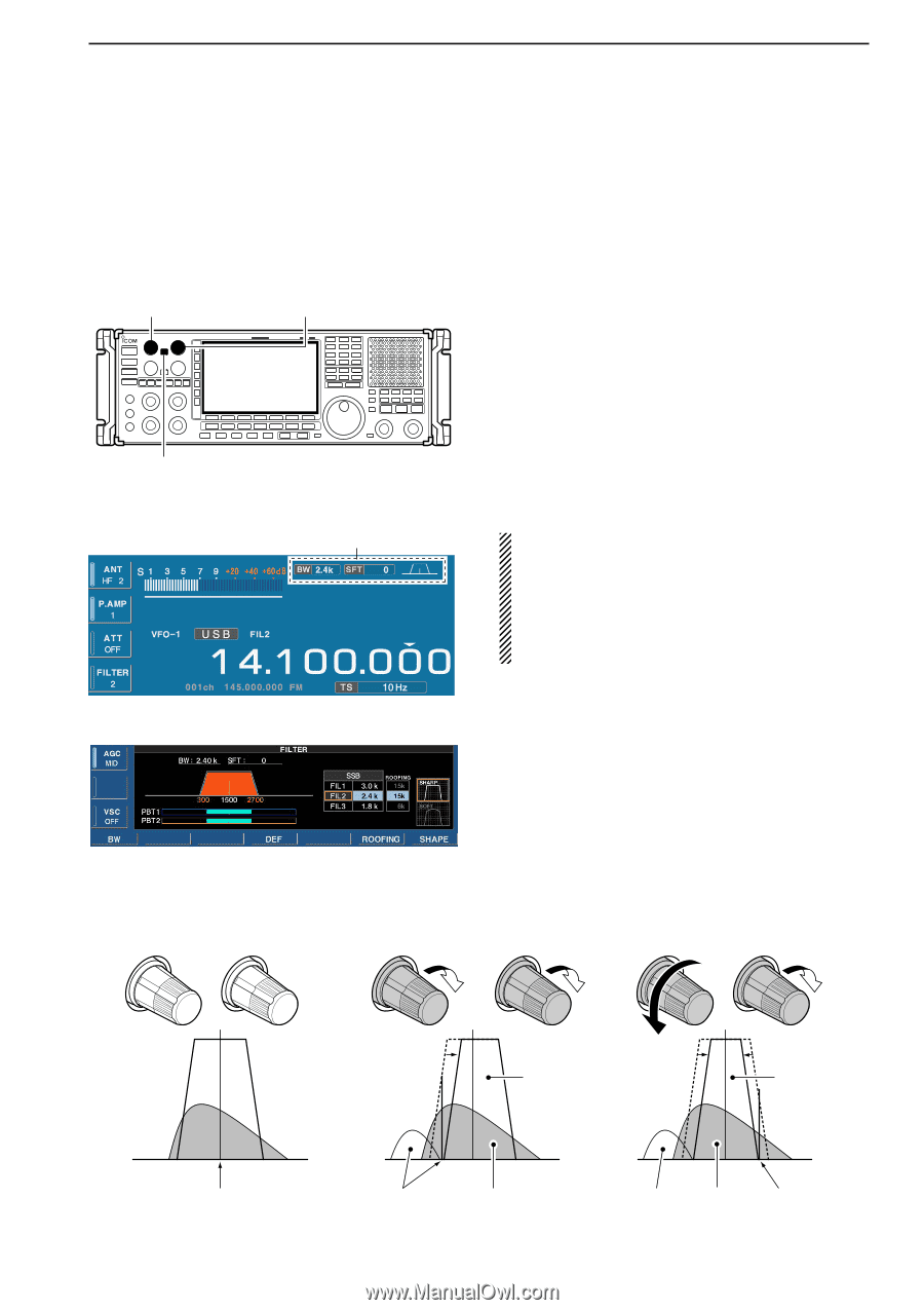
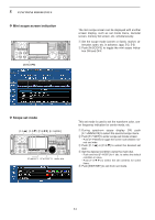
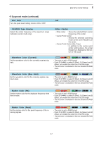
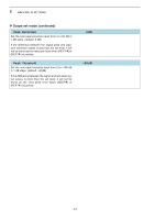
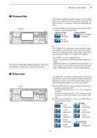
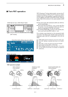
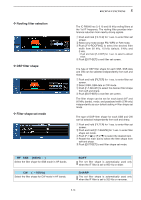
5 RECEIVE FUNCTIONS ■ Twin PBT operation [TWIN PBT] for lower [TWIN PBT] for higher [PBT CLEAR] Shows filter width, shifting value and condition PBT (Passband Tuning) electronically narrows the IF passband width by shifting the IF frequency slightly outside of the IF filter passband, rejecting interference. The IC-R9500 uses DSP for the PBT function. Moving both [TWIN PBT] controls to the same position shifts the IF. ➥ The LCD shows the passband width and shift frequency graphically. ➥ Push and hold [FILTER] for 1 sec. to enter the filter set screen. Current passband width and shift frequency is displayed in the filter set screen. ➥ To set the [TWIN PBT] controls to the center positions, push and hold [PBT CLR] for 1 sec. The variable range depends on the passband width and mode. The edge of the variable range is half of the passband width, and PBT is adjustable in 25 or 50 Hz steps. • [TWIN PBT] should normally be set to the center positions (PBT setting is cleared) when there is no interference. • When PBT is used, the audio tone may be changed. • Not available for FM, WFM or P25 mode. • While rotating [TWIN PBT], noise may occur. This comes from the DSP unit and does not indicate an equipment malfunction. • Filter set screen • PBT operation example Both controls at center position (PBT1) (PBT2) Reducing a lower passband (PBT1) (PBT2) or Passband Reducing both higher and lower passbands (PBT1) (PBT2) Passband IF center frequency Interference Desired signal 5-11 Interference Desired signal Interference
-
 1
1 -
2
-
3
-
4
-
5
-
6
-
7
-
8
-
9
-
10
-
11
-
12
-
13
-
14
-
15
-
16
-
17
-
18
-
19
-
20
-
21
-
22
-
23
-
24
-
25
-
26
-
27
-
28
-
29
-
30
-
31
-
32
-
33
-
34
-
35
-
36
-
37
-
38
-
39
-
40
-
41
-
42
-
43
-
44
-
45
-
46
-
47
-
48
-
49
-
50
-
51
-
52
-
53
-
54
-
55
-
56
-
57
-
58
-
59
-
60
-
61
-
62
-
63
-
64
-
65
-
66
-
67
-
68
-
69
-
70
-
71
-
 72
72 -
 73
73 -
 74
74 -
 75
75 -
 76
76 -
 77
77 -
 78
78 -
 79
79 -
 80
80 -
 81
81 -
 82
82 -
83
-
84
-
85
-
86
-
87
-
88
-
89
-
90
-
91
-
92
-
93
-
94
-
95
-
96
-
97
-
98
-
99
-
100
-
101
-
102
-
103
-
104
-
105
-
106
-
107
-
108
-
109
-
110
-
111
-
112
-
113
-
114
-
115
-
116
-
117
-
118
-
119
-
120
-
121
-
122
-
123
-
124
-
125
-
126
-
127
-
128
-
129
-
130
-
131
-
132
-
133
-
134
-
135
-
136
-
137
-
138
-
139
-
140
-
141
-
142
-
143
-
144
-
145
-
146
-
147
-
148
-
149
-
150
-
151
-
152
-
153
-
154
-
155
-
156
-
157
-
158
-
159
-
160
-
161
-
162
-
163
-
164
-
165
-
166
-
167
-
168
-
169
-
170
-
171
-
172
-
173
-
174
-
175
-
176
-
177
-
178
-
179
-
180
-
181
-
182
-
183
-
184
-
185
-
186
-
187
-
188
-
189
-
190
-
191
-
192
-
193
-
194
 |
 |