Icom IC-R9500 Instruction Manual - Page 16
Memory Transfer Switch [m
 |
View all Icom IC-R9500 manuals
Add to My Manuals
Save this manual to your list of manuals |
Page 16 highlights
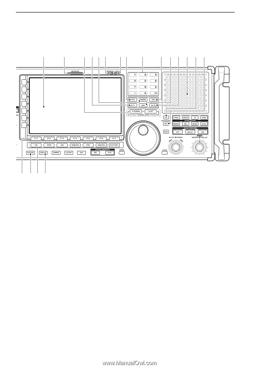
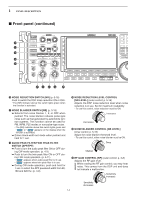
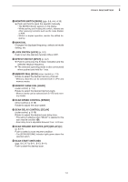
1 PANEL DESCRIPTION ■ Front panel (continued) @6 @7 @8 @9 #0 #1 #2 #3 #4 #5 #6 #7 #8 #9 $0 $1 $2 $3 $4 @6 LCD FUNCTION DISPLAY (p. 1-10) Shows the operating frequency, function switch menus, spectrum scope screen, memory channel screen, set mode settings, etc. @7 RECEIVE INDICATOR [RECEIVE] Lights green while receiving a signal and when the squelch is open. @8 TUNING STEP SWITCHES [▲UP]/[▼DOWM] (p. 3-5) ➥ Select the tuning step for the main dial. Push [▲UP] to select a larger tuning step; push [▼DOWN] to select a smaller tuning step. • 1 Hz, 10 Hz, 100 Hz, 1 kHz, 2.5 kHz, 5 kHz, 6.25 kHz, 9 kHz, 10 kHz, 12.5 kHz, 20 kHz, 25 kHz, 100 kHz and 1 MHz are selectable. • Programmable tuning steps can be set between 0.1 and 999.9 kHz in 0.1 kHz steps. ➠ To set programmable tuning steps, enter the desired steps via the keypad, then push [YUP] or [ZDOWN]. ➥ Push and hold [▲UP] (or [▼DOWN]) for 1 sec. to enter the tuning step select screen. • Unwanted tuning step for each operating mode can be skipped in the tuning step select. @9 MEMORY TRANSFER SWITCH [M≈V] (p. 7-5) Transfers the memory contents to VFO when pushed and held for 1 sec. • This function is available both in VFO and memory modes. #0 MEMORY SWITCH [MEMO] (p.7-3) ➥ Selects the memory mode when pushed. • After pushing one to three digit (0 to 999), pushing the switch selects a memory channel. ➥ Memory bank limit function ON or OFF when pushed and held for 1 sec. #1 REMOTE CONTROL INDICATOR [REMOTE] Lights yellow when a command is received from a PC via CI-V data. • When this indicator lights yellow, all dials, keys or switches other than [LOCAL] are disabled. • This indicator goes OFF, when [LOCAL] is pushed. #2 DIAL LOCK INDICATOR [LOCK] (p. 9-2) Lights orange when the dial lock function is activated. 1-6
-
 1
1 -
2
-
3
-
4
-
5
-
6
-
7
-
8
-
9
-
10
-
 11
11 -
 12
12 -
 13
13 -
 14
14 -
 15
15 -
 16
16 -
 17
17 -
 18
18 -
 19
19 -
 20
20 -
 21
21 -
22
-
23
-
24
-
25
-
26
-
27
-
28
-
29
-
30
-
31
-
32
-
33
-
34
-
35
-
36
-
37
-
38
-
39
-
40
-
41
-
42
-
43
-
44
-
45
-
46
-
47
-
48
-
49
-
50
-
51
-
52
-
53
-
54
-
55
-
56
-
57
-
58
-
59
-
60
-
61
-
62
-
63
-
64
-
65
-
66
-
67
-
68
-
69
-
70
-
71
-
72
-
73
-
74
-
75
-
76
-
77
-
78
-
79
-
80
-
81
-
82
-
83
-
84
-
85
-
86
-
87
-
88
-
89
-
90
-
91
-
92
-
93
-
94
-
95
-
96
-
97
-
98
-
99
-
100
-
101
-
102
-
103
-
104
-
105
-
106
-
107
-
108
-
109
-
110
-
111
-
112
-
113
-
114
-
115
-
116
-
117
-
118
-
119
-
120
-
121
-
122
-
123
-
124
-
125
-
126
-
127
-
128
-
129
-
130
-
131
-
132
-
133
-
134
-
135
-
136
-
137
-
138
-
139
-
140
-
141
-
142
-
143
-
144
-
145
-
146
-
147
-
148
-
149
-
150
-
151
-
152
-
153
-
154
-
155
-
156
-
157
-
158
-
159
-
160
-
161
-
162
-
163
-
164
-
165
-
166
-
167
-
168
-
169
-
170
-
171
-
172
-
173
-
174
-
175
-
176
-
177
-
178
-
179
-
180
-
181
-
182
-
183
-
184
-
185
-
186
-
187
-
188
-
189
-
190
-
191
-
192
-
193
-
194
 |
 |