HP Workstation x2000 hp workstation x2000 - Technical Reference and Troublesho - Page 113
Initialize PIC and DMA
 |
View all HP Workstation x2000 manuals
Add to My Manuals
Save this manual to your list of manuals |
Page 113 highlights
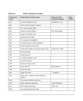
Tests and Error Messages Order in Which POSTs Occur Table 4-1 POST Checkpoint Codes Checkpoint Code POST Routine Description MaxiLife LCD Display Message Beep Codes E5h Check force recovery boot E6h Checksum BIOS ROM E7h Go to BIOS E8h Set huge segment E9h Initialize multiprocessor EAh Initialize OEM special code EBh Initialize PIC and DMA ECh Initialize memory type EDh Initialize memory size EEh Shadow boot block EFh System memory test F0h Initialize interrupt vectors F1h Initialize run time clock F2h Initialize video F3h Initialize system management mode F4h Output one beep before boot F5h Boot to mini DOS F6h Clear huge segment F7h Boot to full DOS a. If the BIOS detects error 2C, 2E, or 30 (base 512KB RAM error), it displays an additional word-bitmap (xxxx) indicating the address line or bits that failed. For example: 2C 0002 means line 1 (bit one set) has failed. 2E 1020 means data bits 12 and 5 (bits 12 and 5 set) have failed in the lower 16 bits. The BIOS also sends the bitmap to the port-80 LED display. It first displays the checkpoint code, followed by a delay, the high-order byte, another delay, then the low-order byte of the error. It repeats this sequence continuously. Chapter 4 113
-
 1
1 -
2
-
3
-
4
-
5
-
6
-
7
-
8
-
9
-
10
-
11
-
12
-
13
-
14
-
15
-
16
-
17
-
18
-
19
-
20
-
21
-
22
-
23
-
24
-
25
-
26
-
27
-
28
-
29
-
30
-
31
-
32
-
33
-
34
-
35
-
36
-
37
-
38
-
39
-
40
-
41
-
42
-
43
-
44
-
45
-
46
-
47
-
48
-
49
-
50
-
51
-
52
-
53
-
54
-
55
-
56
-
57
-
58
-
59
-
60
-
61
-
62
-
63
-
64
-
65
-
66
-
67
-
68
-
69
-
70
-
71
-
72
-
73
-
74
-
75
-
76
-
77
-
78
-
79
-
80
-
81
-
82
-
83
-
84
-
85
-
86
-
87
-
88
-
89
-
90
-
91
-
92
-
93
-
94
-
95
-
96
-
97
-
98
-
99
-
100
-
101
-
102
-
103
-
104
-
105
-
106
-
107
-
 108
108 -
 109
109 -
 110
110 -
 111
111 -
 112
112 -
 113
113 -
 114
114 -
 115
115 -
 116
116 -
 117
117 -
 118
118 -
119
-
120
-
121
-
122
-
123
-
124
-
125
-
126
-
127
-
128
-
129
-
130
-
131
-
132
-
133
-
134
-
135
-
136
-
137
-
138
-
139
-
140
-
141
-
142
-
143
-
144
-
145
-
146
-
147
-
148
-
149
-
150
-
151
-
152
-
153
-
154
-
155
-
156
-
157
-
158
-
159
-
160
-
161
-
162
-
163
-
164
-
165
-
166
-
167
-
168
-
169
-
170
-
171
-
172
-
173
-
174
-
175
-
176
-
177
-
178
-
179
-
180
-
181
-
182
-
183
-
184
-
185
-
186
-
187
-
188
-
189
-
190
-
191
-
192
-
193
-
194
-
195
-
196
-
197
-
198
-
199
-
200
-
201
-
202
-
203
-
204
-
205
-
206
-
207
-
208
-
209
-
210
-
211
-
212
-
213
-
214
-
215
-
216
-
217
-
218
-
219
-
220
-
221
-
222
-
223
-
224
-
225
-
226
-
227
-
228
-
229
-
230
-
231
-
232
-
233
-
234
-
235
-
236
-
237
-
238
-
239
-
240
-
241
-
242
-
243
-
244
-
245
-
246
 |
 |
