HP Workstation x2000 hp workstation x2000 - Technical Reference and Troublesho - Page 155
Removing the Front Bezel, Replacing the Cover and Front Bezel
 |
View all HP Workstation x2000 manuals
Add to My Manuals
Save this manual to your list of manuals |
Page 155 highlights
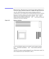
NOTE Figure 6-4 Installing and Replacing Hardware Parts Removing and Replacing the Cover and Front Bezel Removing the Front Bezel The front bezel is divided into two sections: • The upper bezel gives access to three 5.25-inch shelves and two 3.5-inch shelves. • The lower bezel gives access to the control panel. To access the lower bezel, you must first remove the upper bezel. Take care when removing the upper and lower bezels. They are not on a hinge - do not force them open. To remove the upper and lower bezels: 1. Unclip the two clips located on the left-hand side of the bezel. 2. Open the bezel slightly, and then gently push it outwards. See Figure 6-4. Removing the Bezels 1 2 1 Replacing the Cover and Front Bezel 1. Ensure that all internal cables are properly connected and safely routed. 2. If you have removed both sections of the front bezel, first replace the lower bezel. Ensure that the bezel is correctly oriented, align the two Chapter 6 155
-
 1
1 -
2
-
3
-
4
-
5
-
6
-
7
-
8
-
9
-
10
-
11
-
12
-
13
-
14
-
15
-
16
-
17
-
18
-
19
-
20
-
21
-
22
-
23
-
24
-
25
-
26
-
27
-
28
-
29
-
30
-
31
-
32
-
33
-
34
-
35
-
36
-
37
-
38
-
39
-
40
-
41
-
42
-
43
-
44
-
45
-
46
-
47
-
48
-
49
-
50
-
51
-
52
-
53
-
54
-
55
-
56
-
57
-
58
-
59
-
60
-
61
-
62
-
63
-
64
-
65
-
66
-
67
-
68
-
69
-
70
-
71
-
72
-
73
-
74
-
75
-
76
-
77
-
78
-
79
-
80
-
81
-
82
-
83
-
84
-
85
-
86
-
87
-
88
-
89
-
90
-
91
-
92
-
93
-
94
-
95
-
96
-
97
-
98
-
99
-
100
-
101
-
102
-
103
-
104
-
105
-
106
-
107
-
108
-
109
-
110
-
111
-
112
-
113
-
114
-
115
-
116
-
117
-
118
-
119
-
120
-
121
-
122
-
123
-
124
-
125
-
126
-
127
-
128
-
129
-
130
-
131
-
132
-
133
-
134
-
135
-
136
-
137
-
138
-
139
-
140
-
141
-
142
-
143
-
144
-
145
-
146
-
147
-
148
-
149
-
 150
150 -
 151
151 -
 152
152 -
 153
153 -
 154
154 -
 155
155 -
 156
156 -
 157
157 -
 158
158 -
 159
159 -
 160
160 -
161
-
162
-
163
-
164
-
165
-
166
-
167
-
168
-
169
-
170
-
171
-
172
-
173
-
174
-
175
-
176
-
177
-
178
-
179
-
180
-
181
-
182
-
183
-
184
-
185
-
186
-
187
-
188
-
189
-
190
-
191
-
192
-
193
-
194
-
195
-
196
-
197
-
198
-
199
-
200
-
201
-
202
-
203
-
204
-
205
-
206
-
207
-
208
-
209
-
210
-
211
-
212
-
213
-
214
-
215
-
216
-
217
-
218
-
219
-
220
-
221
-
222
-
223
-
224
-
225
-
226
-
227
-
228
-
229
-
230
-
231
-
232
-
233
-
234
-
235
-
236
-
237
-
238
-
239
-
240
-
241
-
242
-
243
-
244
-
245
-
246
 |
 |
