HP Workstation x2000 hp workstation x2000 - Technical Reference and Troublesho - Page 182
Installing the New Processor
 |
View all HP Workstation x2000 manuals
Add to My Manuals
Save this manual to your list of manuals |
Page 182 highlights
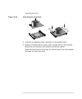
Figure 6-17 Installing and Replacing Hardware Parts Replacing the Processor 6. Open the Zero Insertion Force (ZIF) lever, located at the side of the processor socket, until it is in the vertical position (depending on the socket design, the handle may need to go past vertical), then carefully lift out the processor. To avoid bending the processor pins, keep the processor perfectly flat when removing it. See Figure 6-16. 7. Store the processor in an anti-static bag (for example, the one provided with the replacement processor). Installing the New Processor 1. First ensure the processor is correctly oriented, then carefully lower the new processor into place. When the processor is fully inserted, close the ZIF lever. Inserting the Processor 1 Figure 6-18 2. Carefully remove any thermal bonding material that may remain from the underside of the heatsink. Removing the Bonding Material 2 3. Affix the new thermal interface material (sticker or polymer, provided with the new processor) to the top side of the new processor. 4. Attach the heatsink onto the processor. If there are retaining clips, use them to attach the heatsink. For easier access, attach the rear 182 Chapter 6
-
 1
1 -
2
-
3
-
4
-
5
-
6
-
7
-
8
-
9
-
10
-
11
-
12
-
13
-
14
-
15
-
16
-
17
-
18
-
19
-
20
-
21
-
22
-
23
-
24
-
25
-
26
-
27
-
28
-
29
-
30
-
31
-
32
-
33
-
34
-
35
-
36
-
37
-
38
-
39
-
40
-
41
-
42
-
43
-
44
-
45
-
46
-
47
-
48
-
49
-
50
-
51
-
52
-
53
-
54
-
55
-
56
-
57
-
58
-
59
-
60
-
61
-
62
-
63
-
64
-
65
-
66
-
67
-
68
-
69
-
70
-
71
-
72
-
73
-
74
-
75
-
76
-
77
-
78
-
79
-
80
-
81
-
82
-
83
-
84
-
85
-
86
-
87
-
88
-
89
-
90
-
91
-
92
-
93
-
94
-
95
-
96
-
97
-
98
-
99
-
100
-
101
-
102
-
103
-
104
-
105
-
106
-
107
-
108
-
109
-
110
-
111
-
112
-
113
-
114
-
115
-
116
-
117
-
118
-
119
-
120
-
121
-
122
-
123
-
124
-
125
-
126
-
127
-
128
-
129
-
130
-
131
-
132
-
133
-
134
-
135
-
136
-
137
-
138
-
139
-
140
-
141
-
142
-
143
-
144
-
145
-
146
-
147
-
148
-
149
-
150
-
151
-
152
-
153
-
154
-
155
-
156
-
157
-
158
-
159
-
160
-
161
-
162
-
163
-
164
-
165
-
166
-
167
-
168
-
169
-
170
-
171
-
172
-
173
-
174
-
175
-
176
-
 177
177 -
 178
178 -
 179
179 -
 180
180 -
 181
181 -
 182
182 -
 183
183 -
 184
184 -
 185
185 -
 186
186 -
 187
187 -
188
-
189
-
190
-
191
-
192
-
193
-
194
-
195
-
196
-
197
-
198
-
199
-
200
-
201
-
202
-
203
-
204
-
205
-
206
-
207
-
208
-
209
-
210
-
211
-
212
-
213
-
214
-
215
-
216
-
217
-
218
-
219
-
220
-
221
-
222
-
223
-
224
-
225
-
226
-
227
-
228
-
229
-
230
-
231
-
232
-
233
-
234
-
235
-
236
-
237
-
238
-
239
-
240
-
241
-
242
-
243
-
244
-
245
-
246
 |
 |
