HP Workstation x2000 hp workstation x2000 - Technical Reference and Troublesho - Page 64
HP MaxiLife Hardware-Monitoring Chip
 |
View all HP Workstation x2000 manuals
Add to My Manuals
Save this manual to your list of manuals |
Page 64 highlights
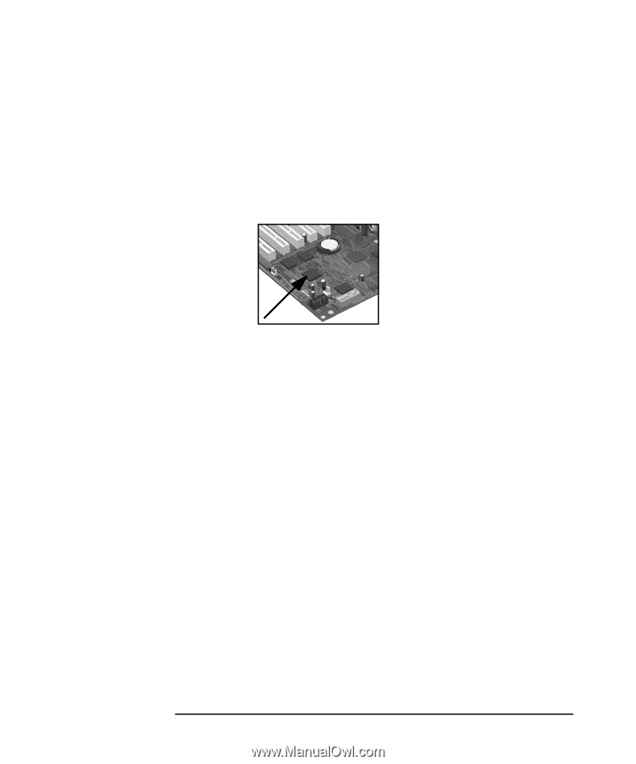
Figure 2-11 System Board The Input/Output Controller Hub 2 (82801BA) • Status panel management (lock button, LEDs) • Hardware monitoring (temperature and voltage) • Early diagnostics (CPU, memory, PLLs, boot start) • Run-time diagnostics (CPU errors) • Fan speed regulation • Other miscellaneous functions (such as special OK/FAIL symbols based on a smiling face) HP MaxiLife Hardware-Monitoring Chip The integrated microprocessor includes the following: • Synopsys cell based on Dallas "8052" equivalent • 2KB boot ROM • 256 bytes of data RAM • I2C cell • Analog-to-Digital (ADC) with five entries • Additional glue logic for interrupt control, fan regulation, and a status panel control MaxiLife downloads its code in 96 milliseconds from an I2C serial EEPROM. The total firmware (MaxiLife 8051-code, running in RAM) size is 14KB. As it exceeds the 2KB program RAM space, a paging mechanism swaps code as necessary, based on a 512-byte buffer. The first 2KB pages of firmware code is crucial because it controls the initial power on/reset to boot the system. This initial page is checked with a null-checksum test and the presence of MaxiLife markers (located just below the 2KB limit). MaxiLife is not accessible in I/O space or memory space of the system platform, but only through the SMBus (which is a subset of the I2C bus), via the ICH2. Its I2C cell may operate either in slave or master mode, switched by firmware, or automatically in the event of Arbitration loss. As a monitoring chip, MaxiLife reports critical errors at start-up, and is therefore powered by Vstandby (3.3V) power. For MaxiLife to work, the workstation must be connected to a grounded outlet. This enables the 64 Chapter 2
-
 1
1 -
2
-
3
-
4
-
5
-
6
-
7
-
8
-
9
-
10
-
11
-
12
-
13
-
14
-
15
-
16
-
17
-
18
-
19
-
20
-
21
-
22
-
23
-
24
-
25
-
26
-
27
-
28
-
29
-
30
-
31
-
32
-
33
-
34
-
35
-
36
-
37
-
38
-
39
-
40
-
41
-
42
-
43
-
44
-
45
-
46
-
47
-
48
-
49
-
50
-
51
-
52
-
53
-
54
-
55
-
56
-
57
-
58
-
 59
59 -
 60
60 -
 61
61 -
 62
62 -
 63
63 -
 64
64 -
 65
65 -
 66
66 -
 67
67 -
 68
68 -
 69
69 -
70
-
71
-
72
-
73
-
74
-
75
-
76
-
77
-
78
-
79
-
80
-
81
-
82
-
83
-
84
-
85
-
86
-
87
-
88
-
89
-
90
-
91
-
92
-
93
-
94
-
95
-
96
-
97
-
98
-
99
-
100
-
101
-
102
-
103
-
104
-
105
-
106
-
107
-
108
-
109
-
110
-
111
-
112
-
113
-
114
-
115
-
116
-
117
-
118
-
119
-
120
-
121
-
122
-
123
-
124
-
125
-
126
-
127
-
128
-
129
-
130
-
131
-
132
-
133
-
134
-
135
-
136
-
137
-
138
-
139
-
140
-
141
-
142
-
143
-
144
-
145
-
146
-
147
-
148
-
149
-
150
-
151
-
152
-
153
-
154
-
155
-
156
-
157
-
158
-
159
-
160
-
161
-
162
-
163
-
164
-
165
-
166
-
167
-
168
-
169
-
170
-
171
-
172
-
173
-
174
-
175
-
176
-
177
-
178
-
179
-
180
-
181
-
182
-
183
-
184
-
185
-
186
-
187
-
188
-
189
-
190
-
191
-
192
-
193
-
194
-
195
-
196
-
197
-
198
-
199
-
200
-
201
-
202
-
203
-
204
-
205
-
206
-
207
-
208
-
209
-
210
-
211
-
212
-
213
-
214
-
215
-
216
-
217
-
218
-
219
-
220
-
221
-
222
-
223
-
224
-
225
-
226
-
227
-
228
-
229
-
230
-
231
-
232
-
233
-
234
-
235
-
236
-
237
-
238
-
239
-
240
-
241
-
242
-
243
-
244
-
245
-
246
 |
 |