HP Visualize J5000 hp Visualize J5000, J7000 workstations owner's guide (a4978 - Page 106
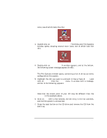
Controls and Indicators, DDS-3 Drive Controls and Indicators, Table 5-2
 |
View all HP Visualize J5000 manuals
Add to My Manuals
Save this manual to your list of manuals |
Page 106 highlights
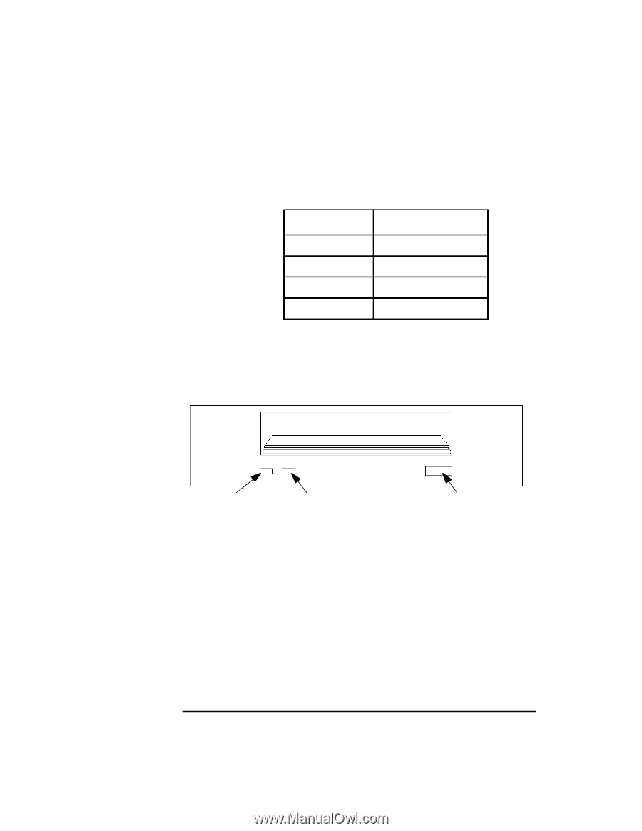
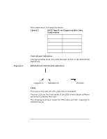
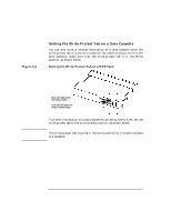
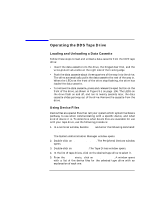
Figure 5-1 Using Your Digital Data Storage (DDS) Tape Drive DDS Tape Drive and Cassette Descriptions With compression, the capacities double: Table 5-2 DDS3 Tape Drive Capacities With Data Compression Tape Length 60 meters 90 meters 120 meters 125 meters DDS3 Tape Drive 2.6 GB 4.0 GB 8.0 GB 24.0 GB Controls and Indicators The figures below show the LEDs and eject button of the DDS-format tape drives. DDS-3 Drive Controls and Indicators Left (green) LED Right (amber) LED Eject Button LEDs This section describes the LED codes that are displayed. The two LEDs on the front panels of the DDS drives indicate different activities or problems that occur. The following illustration shows the LED codes and their meanings for the DDS3 drive. 106 Chapter 5
-
 1
1 -
2
-
3
-
4
-
5
-
6
-
7
-
8
-
9
-
10
-
11
-
12
-
13
-
14
-
15
-
16
-
17
-
18
-
19
-
20
-
21
-
22
-
23
-
24
-
25
-
26
-
27
-
28
-
29
-
30
-
31
-
32
-
33
-
34
-
35
-
36
-
37
-
38
-
39
-
40
-
41
-
42
-
43
-
44
-
45
-
46
-
47
-
48
-
49
-
50
-
51
-
52
-
53
-
54
-
55
-
56
-
57
-
58
-
59
-
60
-
61
-
62
-
63
-
64
-
65
-
66
-
67
-
68
-
69
-
70
-
71
-
72
-
73
-
74
-
75
-
76
-
77
-
78
-
79
-
80
-
81
-
82
-
83
-
84
-
85
-
86
-
87
-
88
-
89
-
90
-
91
-
92
-
93
-
94
-
95
-
96
-
97
-
98
-
99
-
100
-
 101
101 -
 102
102 -
 103
103 -
 104
104 -
 105
105 -
 106
106 -
 107
107 -
 108
108 -
 109
109 -
 110
110 -
 111
111 -
112
-
113
-
114
-
115
-
116
-
117
-
118
-
119
-
120
-
121
-
122
-
123
-
124
-
125
-
126
-
127
-
128
-
129
-
130
-
131
-
132
-
133
-
134
-
135
-
136
-
137
-
138
-
139
-
140
-
141
-
142
-
143
-
144
-
145
-
146
-
147
-
148
-
149
-
150
-
151
-
152
-
153
-
154
-
155
-
156
-
157
-
158
-
159
-
160
-
161
-
162
-
163
-
164
-
165
-
166
-
167
-
168
-
169
-
170
-
171
-
172
-
173
-
174
-
175
-
176
-
177
-
178
-
179
-
180
-
181
-
182
-
183
-
184
-
185
-
186
-
187
-
188
-
189
-
190
-
191
-
192
-
193
-
194
-
195
-
196
-
197
-
198
-
199
-
200
-
201
-
202
-
203
-
204
-
205
-
206
-
207
-
208
-
209
-
210
-
211
-
212
 |
 |