HP Visualize J5000 hp Visualize J5000, J7000 workstations owner's guide (a4978 - Page 69
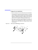
Removing the DDS/Floppy Drive Filler Panels, Floppy Drive Installation
 |
View all HP Visualize J5000 manuals
Add to My Manuals
Save this manual to your list of manuals |
Page 69 highlights
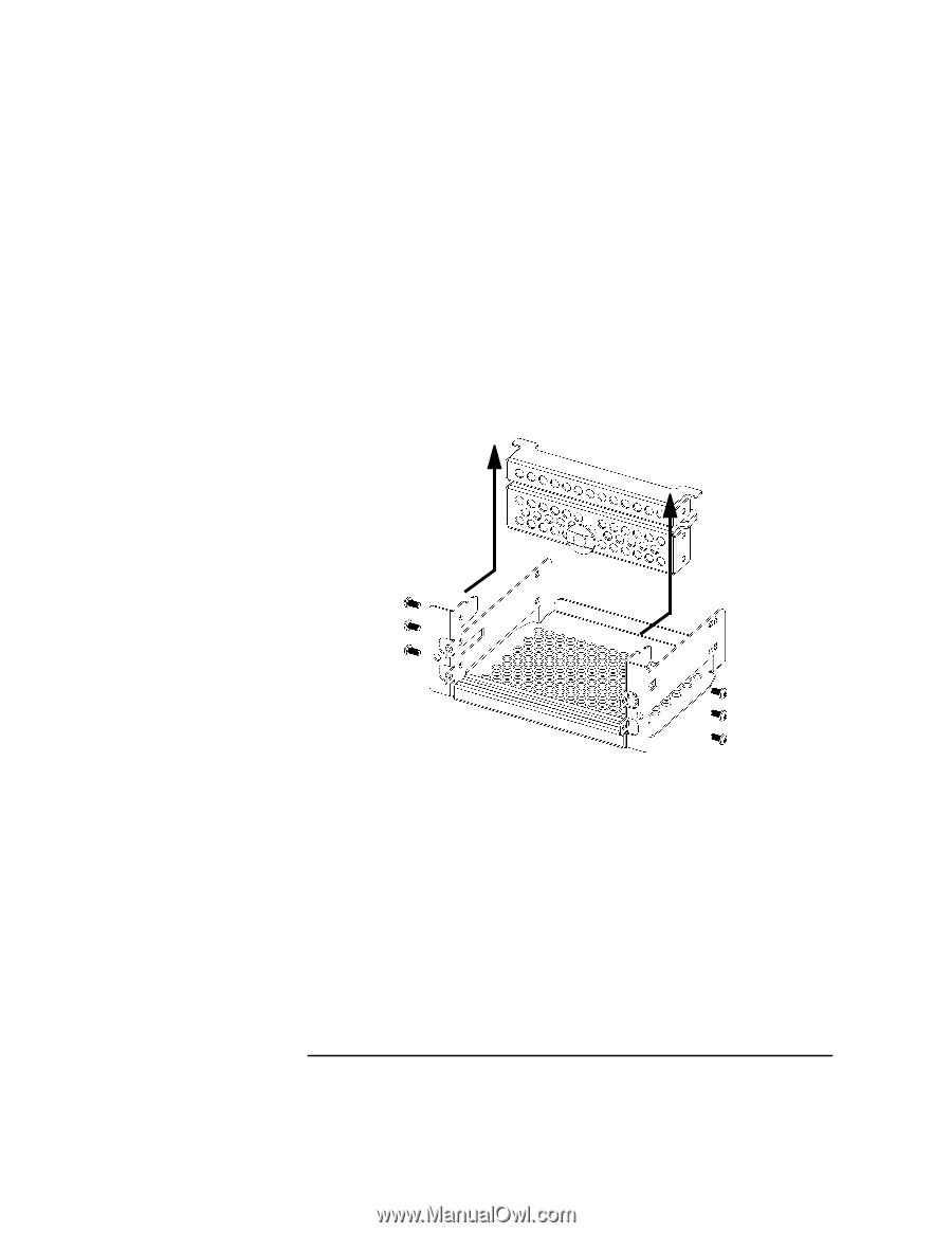
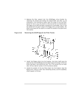
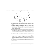
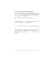
Changing Your Computer's Hardware Configuration Floppy Drive Installation Figure 2-22 3. Remove the filler panels from the DDS/floppy drive bracket by removing the screws and sliding the panels back and then up, as indicated in the illustration below. Save the larger of the two filler panels for future use; the smaller of the two will be re-installed after the floppy drive itself has been installed onto the bracket. Four of the six screws will be used to secure the floppy drive to the bracket; the other two screws will be used to re-install the smaller filler panel onto the bracket. Removing the DDS/Floppy Drive Filler Panels 4. Install the floppy drive into the bracket: the drive itself must be inserted into the DDS/floppy drive bracket where the larger of the two fillers had been, and secured by four Torx T-10 screws (two on each side; the four bottom screws in the illustration above). 5. Install the smaller of the two fillers back into the bracket, atop the floppy drive. Secure it with two remaining screws, and the assembly should appear as follows. Chapter 2 69
-
 1
1 -
2
-
3
-
4
-
5
-
6
-
7
-
8
-
9
-
10
-
11
-
12
-
13
-
14
-
15
-
16
-
17
-
18
-
19
-
20
-
21
-
22
-
23
-
24
-
25
-
26
-
27
-
28
-
29
-
30
-
31
-
32
-
33
-
34
-
35
-
36
-
37
-
38
-
39
-
40
-
41
-
42
-
43
-
44
-
45
-
46
-
47
-
48
-
49
-
50
-
51
-
52
-
53
-
54
-
55
-
56
-
57
-
58
-
59
-
60
-
61
-
62
-
63
-
 64
64 -
 65
65 -
 66
66 -
 67
67 -
 68
68 -
 69
69 -
 70
70 -
 71
71 -
 72
72 -
 73
73 -
 74
74 -
75
-
76
-
77
-
78
-
79
-
80
-
81
-
82
-
83
-
84
-
85
-
86
-
87
-
88
-
89
-
90
-
91
-
92
-
93
-
94
-
95
-
96
-
97
-
98
-
99
-
100
-
101
-
102
-
103
-
104
-
105
-
106
-
107
-
108
-
109
-
110
-
111
-
112
-
113
-
114
-
115
-
116
-
117
-
118
-
119
-
120
-
121
-
122
-
123
-
124
-
125
-
126
-
127
-
128
-
129
-
130
-
131
-
132
-
133
-
134
-
135
-
136
-
137
-
138
-
139
-
140
-
141
-
142
-
143
-
144
-
145
-
146
-
147
-
148
-
149
-
150
-
151
-
152
-
153
-
154
-
155
-
156
-
157
-
158
-
159
-
160
-
161
-
162
-
163
-
164
-
165
-
166
-
167
-
168
-
169
-
170
-
171
-
172
-
173
-
174
-
175
-
176
-
177
-
178
-
179
-
180
-
181
-
182
-
183
-
184
-
185
-
186
-
187
-
188
-
189
-
190
-
191
-
192
-
193
-
194
-
195
-
196
-
197
-
198
-
199
-
200
-
201
-
202
-
203
-
204
-
205
-
206
-
207
-
208
-
209
-
210
-
211
-
212
 |
 |