HP Visualize J5000 hp Visualize J5000, J7000 workstations owner's guide (a4978 - Page 68
Floppy Drive Installation, Removing the DDS/Floppy Drive Bracket
 |
View all HP Visualize J5000 manuals
Add to My Manuals
Save this manual to your list of manuals |
Page 68 highlights
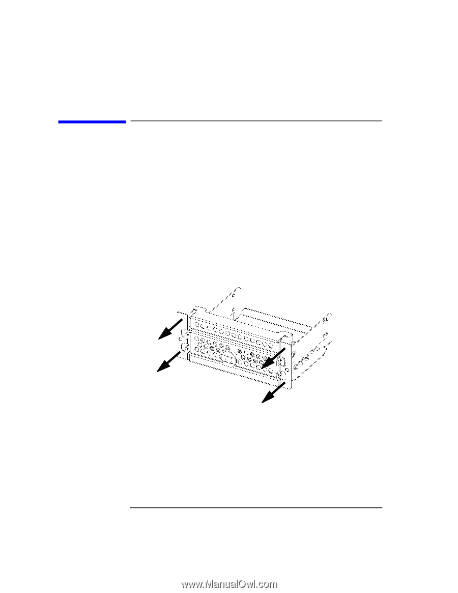
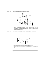
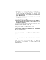
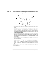
Changing Your Computer's Hardware Configuration Floppy Drive Installation Figure 2-21 Floppy Drive Installation To install a PC floppy drive into the J5000/J7000, follow the steps below: 1. Using standard static-suppression practices (described in the Preface to this document), remove the computer's front panel, as described earlier in "Removing the Front Panel" on page 44, and top cover, as described in "Opening the Top Cover" on page 46. Then remove the floppy-drive bay's EMI (electromagnetic interference) cover-the thin metal cover that is snapped in place above the floppy drive bay. 2. Remove the two screws securing the DDS/floppy drive bracket to the main chassis, and pull the bracket straight out. The bracket is referred to as the "DDS/floppy drive bracket" because the same bracket can house either a DDS drive or a floppy drive (but not both simultaneously). Removing the DDS/Floppy Drive Bracket 68 Chapter 2
-
 1
1 -
2
-
3
-
4
-
5
-
6
-
7
-
8
-
9
-
10
-
11
-
12
-
13
-
14
-
15
-
16
-
17
-
18
-
19
-
20
-
21
-
22
-
23
-
24
-
25
-
26
-
27
-
28
-
29
-
30
-
31
-
32
-
33
-
34
-
35
-
36
-
37
-
38
-
39
-
40
-
41
-
42
-
43
-
44
-
45
-
46
-
47
-
48
-
49
-
50
-
51
-
52
-
53
-
54
-
55
-
56
-
57
-
58
-
59
-
60
-
61
-
62
-
 63
63 -
 64
64 -
 65
65 -
 66
66 -
 67
67 -
 68
68 -
 69
69 -
 70
70 -
 71
71 -
 72
72 -
 73
73 -
74
-
75
-
76
-
77
-
78
-
79
-
80
-
81
-
82
-
83
-
84
-
85
-
86
-
87
-
88
-
89
-
90
-
91
-
92
-
93
-
94
-
95
-
96
-
97
-
98
-
99
-
100
-
101
-
102
-
103
-
104
-
105
-
106
-
107
-
108
-
109
-
110
-
111
-
112
-
113
-
114
-
115
-
116
-
117
-
118
-
119
-
120
-
121
-
122
-
123
-
124
-
125
-
126
-
127
-
128
-
129
-
130
-
131
-
132
-
133
-
134
-
135
-
136
-
137
-
138
-
139
-
140
-
141
-
142
-
143
-
144
-
145
-
146
-
147
-
148
-
149
-
150
-
151
-
152
-
153
-
154
-
155
-
156
-
157
-
158
-
159
-
160
-
161
-
162
-
163
-
164
-
165
-
166
-
167
-
168
-
169
-
170
-
171
-
172
-
173
-
174
-
175
-
176
-
177
-
178
-
179
-
180
-
181
-
182
-
183
-
184
-
185
-
186
-
187
-
188
-
189
-
190
-
191
-
192
-
193
-
194
-
195
-
196
-
197
-
198
-
199
-
200
-
201
-
202
-
203
-
204
-
205
-
206
-
207
-
208
-
209
-
210
-
211
-
212
 |
 |