HP Visualize J5000 hp Visualize J5000, J7000 workstations owner's guide (a4978 - Page 28
RS-232C Serial Input/Output Connectors, SCSI Connectors, Table 1-3, Serial I/O Pins
 |
View all HP Visualize J5000 manuals
Add to My Manuals
Save this manual to your list of manuals |
Page 28 highlights
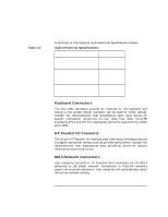
Table 1-3 System Overview System Unit Rear Panel Connectors RS-232C Serial Input/Output Connectors You can attach peripheral devices to the RS-232C Serial Input/Output (SIO) ports on this computer. Peripheral devices include printers, plotters, modems, and scanners. Consult the documentation that accompanies each pointing or peripheral device for specific information concerning its use. The SIO ports are programmable; that is, you can choose attributes such as bit rate, character length, parity, and stop bits either by selecting the corresponding device file (in /dev), or by using SAM (the System Administration Manager). The SIO ports are used as an interface for serial asynchronous devices to the CPU. The ports operate at up to a 115.2Kbaud rate. The table below shows the SIO connector pin listings. The serial connectors are 9-pin D-sub connectors. Signal names are those specified in the EIA RS-232 standard. Serial I/O Pins Pin No. 1 2 3 4 5 6 7 8 9 Signal DCD RXD TXD DTR GND DSR RTS CTS RI Description Data Carrier Detect Receive Data Transmit Data Data Terminal Ready Ground Data Set Ready Request To Send Clear To Send Ring Indicator SCSI Connectors Use the Narrow Single-Ended SCSI connector and/or the Wide LVD (Low-Voltage Differential) SCSI connectors to connect external SCSI devices such as hard disk drives, optical disk drives, DDS-format tape 28 Chapter 1
-
 1
1 -
2
-
3
-
4
-
5
-
6
-
7
-
8
-
9
-
10
-
11
-
12
-
13
-
14
-
15
-
16
-
17
-
18
-
19
-
20
-
21
-
22
-
 23
23 -
 24
24 -
 25
25 -
 26
26 -
 27
27 -
 28
28 -
 29
29 -
 30
30 -
 31
31 -
 32
32 -
 33
33 -
34
-
35
-
36
-
37
-
38
-
39
-
40
-
41
-
42
-
43
-
44
-
45
-
46
-
47
-
48
-
49
-
50
-
51
-
52
-
53
-
54
-
55
-
56
-
57
-
58
-
59
-
60
-
61
-
62
-
63
-
64
-
65
-
66
-
67
-
68
-
69
-
70
-
71
-
72
-
73
-
74
-
75
-
76
-
77
-
78
-
79
-
80
-
81
-
82
-
83
-
84
-
85
-
86
-
87
-
88
-
89
-
90
-
91
-
92
-
93
-
94
-
95
-
96
-
97
-
98
-
99
-
100
-
101
-
102
-
103
-
104
-
105
-
106
-
107
-
108
-
109
-
110
-
111
-
112
-
113
-
114
-
115
-
116
-
117
-
118
-
119
-
120
-
121
-
122
-
123
-
124
-
125
-
126
-
127
-
128
-
129
-
130
-
131
-
132
-
133
-
134
-
135
-
136
-
137
-
138
-
139
-
140
-
141
-
142
-
143
-
144
-
145
-
146
-
147
-
148
-
149
-
150
-
151
-
152
-
153
-
154
-
155
-
156
-
157
-
158
-
159
-
160
-
161
-
162
-
163
-
164
-
165
-
166
-
167
-
168
-
169
-
170
-
171
-
172
-
173
-
174
-
175
-
176
-
177
-
178
-
179
-
180
-
181
-
182
-
183
-
184
-
185
-
186
-
187
-
188
-
189
-
190
-
191
-
192
-
193
-
194
-
195
-
196
-
197
-
198
-
199
-
200
-
201
-
202
-
203
-
204
-
205
-
206
-
207
-
208
-
209
-
210
-
211
-
212
 |
 |
