HP Visualize J5000 hp Visualize J5000, J7000 workstations owner's guide (a4978 - Page 25
System Unit Rear Panel Connectors
 |
View all HP Visualize J5000 manuals
Add to My Manuals
Save this manual to your list of manuals |
Page 25 highlights
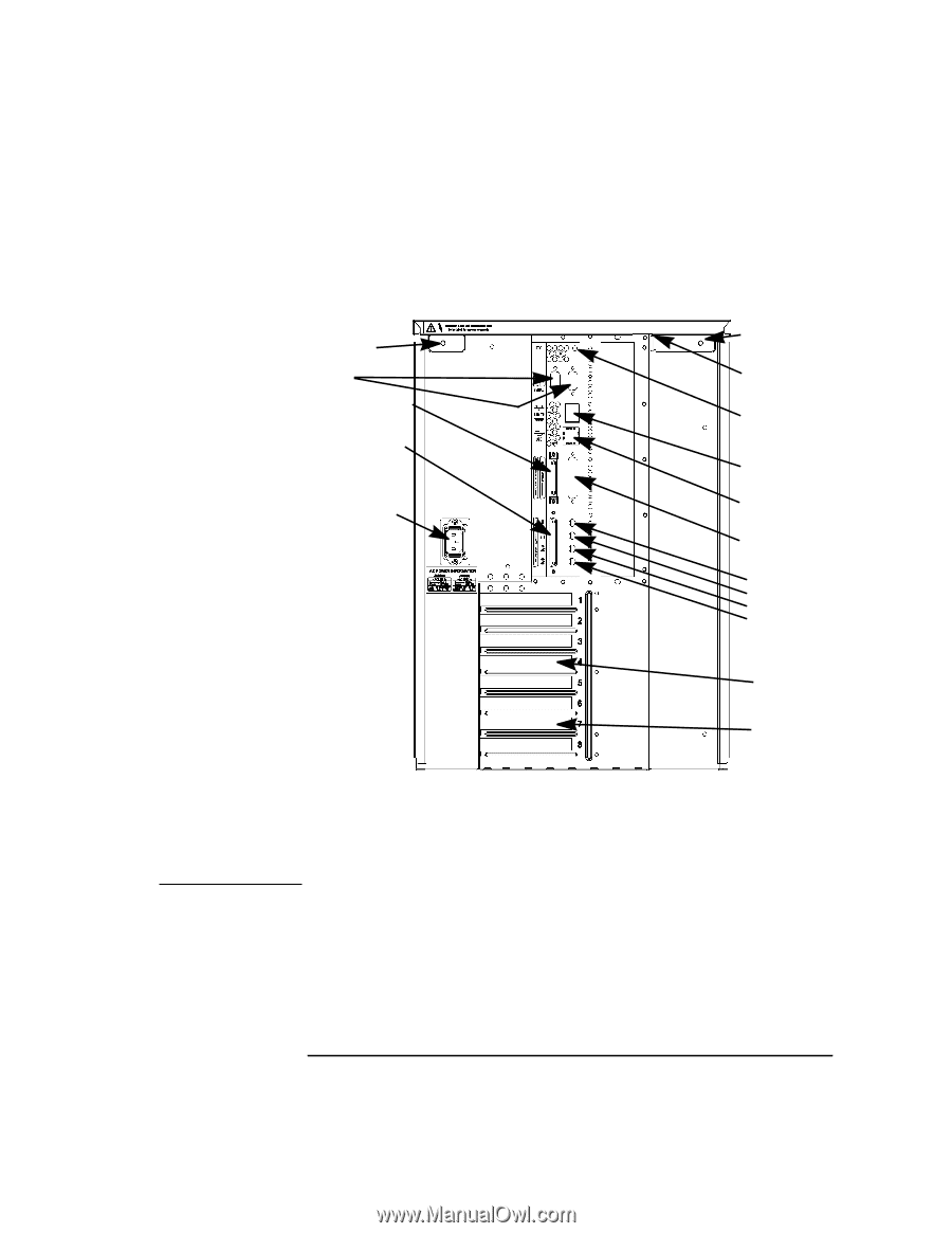
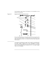
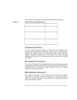
Figure 1-4 NOTE System Overview System Unit Rear Panel Connectors The illustration below shows the locations of the connectors on the system unit's rear panel. System Unit Rear Panel Connectors Power Supply Interlock screw (Torx T-15) RS-232 Narrow SE SCSI Wide LVD SCSI Thumbscrew (T-15) Security Tab TOC/Interrupt 100Base-T AC Power (Auto-sensing) {I/O Slots USB Parallel Audio: Mic In Headphones Line out Line in Secondary Graphics Slot (Slot 4) Primary Graphics Slot (Slot 7) The two T-15 thumbscrews in the upper corners of the rear panel are the keys to opening the machine: removing these two screws allows the top panel to be removed, which in turn allows the left and right side panels to be removed. The upper-left thumbscrew (as seen from the back) is interlocked with the power supply: loosening that screw disengages the power, minimizing the shock danger while servicing. Make sure the interlocked screw is firmly tightened when closing the unit, or the power supply might still be disengaged. Chapter 1 25
-
 1
1 -
2
-
3
-
4
-
5
-
6
-
7
-
8
-
9
-
10
-
11
-
12
-
13
-
14
-
15
-
16
-
17
-
18
-
19
-
 20
20 -
 21
21 -
 22
22 -
 23
23 -
 24
24 -
 25
25 -
 26
26 -
 27
27 -
 28
28 -
 29
29 -
 30
30 -
31
-
32
-
33
-
34
-
35
-
36
-
37
-
38
-
39
-
40
-
41
-
42
-
43
-
44
-
45
-
46
-
47
-
48
-
49
-
50
-
51
-
52
-
53
-
54
-
55
-
56
-
57
-
58
-
59
-
60
-
61
-
62
-
63
-
64
-
65
-
66
-
67
-
68
-
69
-
70
-
71
-
72
-
73
-
74
-
75
-
76
-
77
-
78
-
79
-
80
-
81
-
82
-
83
-
84
-
85
-
86
-
87
-
88
-
89
-
90
-
91
-
92
-
93
-
94
-
95
-
96
-
97
-
98
-
99
-
100
-
101
-
102
-
103
-
104
-
105
-
106
-
107
-
108
-
109
-
110
-
111
-
112
-
113
-
114
-
115
-
116
-
117
-
118
-
119
-
120
-
121
-
122
-
123
-
124
-
125
-
126
-
127
-
128
-
129
-
130
-
131
-
132
-
133
-
134
-
135
-
136
-
137
-
138
-
139
-
140
-
141
-
142
-
143
-
144
-
145
-
146
-
147
-
148
-
149
-
150
-
151
-
152
-
153
-
154
-
155
-
156
-
157
-
158
-
159
-
160
-
161
-
162
-
163
-
164
-
165
-
166
-
167
-
168
-
169
-
170
-
171
-
172
-
173
-
174
-
175
-
176
-
177
-
178
-
179
-
180
-
181
-
182
-
183
-
184
-
185
-
186
-
187
-
188
-
189
-
190
-
191
-
192
-
193
-
194
-
195
-
196
-
197
-
198
-
199
-
200
-
201
-
202
-
203
-
204
-
205
-
206
-
207
-
208
-
209
-
210
-
211
-
212
 |
 |