HP Visualize J5000 hp Visualize J5000, J7000 workstations owner's guide (a4978 - Page 57
PCI Slots in a J5000/J7000
 |
View all HP Visualize J5000 manuals
Add to My Manuals
Save this manual to your list of manuals |
Page 57 highlights
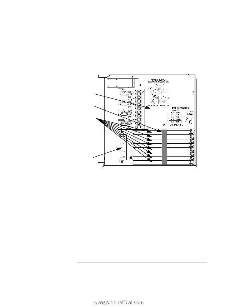
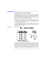
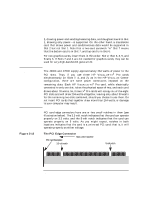
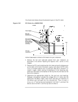
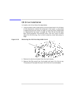
Figure 2-13 Changing Your Computer's Hardware Configuration Installing a PCI-Type I/O Board The illustration below shows the physical layout of the PCI slots: PCI Slots in a J5000/J7000 Power Supply PCI Card Retaining Clip PCI Card Slots (Slot 7 is the primary graphics slot; Slot 4 is the Slot: secondary) 1 2 3 4 5 PCI Card 6 Cooling Fan 7 8 Follow these steps to install a PCI board into your computer: 1. Remove the top and right-side panels from your computer, as described in the section "Opening the System Unit," earlier in this chapter. 2. Remove the PCI card retaining clip-the instructions for doing so are on the label on the side of the power supply, right above the PCI slots. This is a simple snap-on clip; no tools are required to remove it or install it again. (Note: during re-installation of the retaining clip, make sure the hook on the bottom of the clip fits into the hole on the floor of the chassis.) 3. Determine the appropriate slot(s) for the card you are inserting. Relevant information includes the voltage (3.3 or 5 volts) and the speed (33 or 66 MHz). Again, when multi-card sets are inserted, it's the bottom card that goes into the indicated slot. Thus, to insert a VISUALIZE FX6 card (a two-card sandwich) "into" Slot 7, you'd put the bottom card into Slot 7, and the top card into Slot 6. Chapter 2 57
-
 1
1 -
2
-
3
-
4
-
5
-
6
-
7
-
8
-
9
-
10
-
11
-
12
-
13
-
14
-
15
-
16
-
17
-
18
-
19
-
20
-
21
-
22
-
23
-
24
-
25
-
26
-
27
-
28
-
29
-
30
-
31
-
32
-
33
-
34
-
35
-
36
-
37
-
38
-
39
-
40
-
41
-
42
-
43
-
44
-
45
-
46
-
47
-
48
-
49
-
50
-
51
-
 52
52 -
 53
53 -
 54
54 -
 55
55 -
 56
56 -
 57
57 -
 58
58 -
 59
59 -
 60
60 -
 61
61 -
 62
62 -
63
-
64
-
65
-
66
-
67
-
68
-
69
-
70
-
71
-
72
-
73
-
74
-
75
-
76
-
77
-
78
-
79
-
80
-
81
-
82
-
83
-
84
-
85
-
86
-
87
-
88
-
89
-
90
-
91
-
92
-
93
-
94
-
95
-
96
-
97
-
98
-
99
-
100
-
101
-
102
-
103
-
104
-
105
-
106
-
107
-
108
-
109
-
110
-
111
-
112
-
113
-
114
-
115
-
116
-
117
-
118
-
119
-
120
-
121
-
122
-
123
-
124
-
125
-
126
-
127
-
128
-
129
-
130
-
131
-
132
-
133
-
134
-
135
-
136
-
137
-
138
-
139
-
140
-
141
-
142
-
143
-
144
-
145
-
146
-
147
-
148
-
149
-
150
-
151
-
152
-
153
-
154
-
155
-
156
-
157
-
158
-
159
-
160
-
161
-
162
-
163
-
164
-
165
-
166
-
167
-
168
-
169
-
170
-
171
-
172
-
173
-
174
-
175
-
176
-
177
-
178
-
179
-
180
-
181
-
182
-
183
-
184
-
185
-
186
-
187
-
188
-
189
-
190
-
191
-
192
-
193
-
194
-
195
-
196
-
197
-
198
-
199
-
200
-
201
-
202
-
203
-
204
-
205
-
206
-
207
-
208
-
209
-
210
-
211
-
212
 |
 |