HP Visualize J5000 hp Visualize J5000, J7000 workstations owner's guide (a4978 - Page 53
Inserting a DIMM, Removing a DIMM
 |
View all HP Visualize J5000 manuals
Add to My Manuals
Save this manual to your list of manuals |
Page 53 highlights
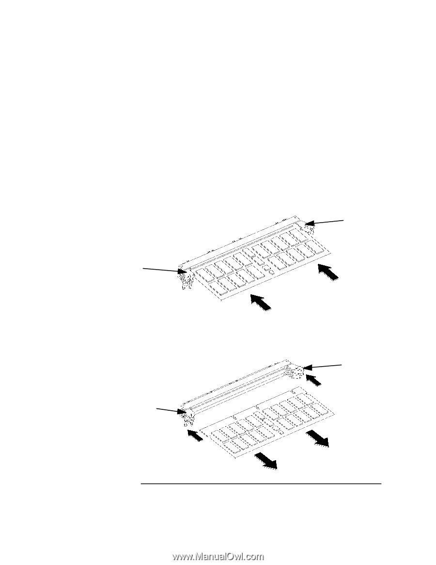
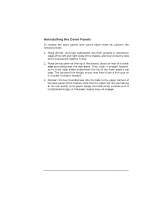
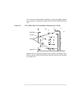
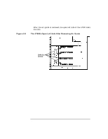
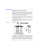
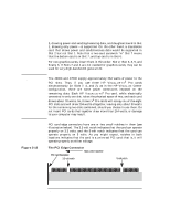
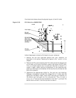
Changing Your Computer's Hardware Configuration Installing Memory Figure 2-9 2. Install DIMMs in the order indicated in Figure 2-5 on page 49, or on the label on the floor of the chassis (the J7000 requires DIMMs to be installed in pairs of the same size). Make sure the DIMM-removal tabs are angled out-away from each other. The DIMMs are keyed; that is, there are notches in the edge (see Figure 2-10, below) that prevent the DIMM from being inserted upside down. Once the DIMM is oriented correctly (the notches in the DIMM lining up with the bumps in the slot), press firmly and evenly on each DIMM to ensure that it seats properly; the DIMM-removal tabs will rotate to become parallel as the DIMM is inserted: Inserting a DIMM Black DIMM-removal tab White DIMM-removal tab Figure 2-10 3. To remove a DIMM, push these tabs away from each other, and the DIMM will be removed from its socket. Removing a DIMM Black White Chapter 2 53
-
 1
1 -
2
-
3
-
4
-
5
-
6
-
7
-
8
-
9
-
10
-
11
-
12
-
13
-
14
-
15
-
16
-
17
-
18
-
19
-
20
-
21
-
22
-
23
-
24
-
25
-
26
-
27
-
28
-
29
-
30
-
31
-
32
-
33
-
34
-
35
-
36
-
37
-
38
-
39
-
40
-
41
-
42
-
43
-
44
-
45
-
46
-
47
-
 48
48 -
 49
49 -
 50
50 -
 51
51 -
 52
52 -
 53
53 -
 54
54 -
 55
55 -
 56
56 -
 57
57 -
 58
58 -
59
-
60
-
61
-
62
-
63
-
64
-
65
-
66
-
67
-
68
-
69
-
70
-
71
-
72
-
73
-
74
-
75
-
76
-
77
-
78
-
79
-
80
-
81
-
82
-
83
-
84
-
85
-
86
-
87
-
88
-
89
-
90
-
91
-
92
-
93
-
94
-
95
-
96
-
97
-
98
-
99
-
100
-
101
-
102
-
103
-
104
-
105
-
106
-
107
-
108
-
109
-
110
-
111
-
112
-
113
-
114
-
115
-
116
-
117
-
118
-
119
-
120
-
121
-
122
-
123
-
124
-
125
-
126
-
127
-
128
-
129
-
130
-
131
-
132
-
133
-
134
-
135
-
136
-
137
-
138
-
139
-
140
-
141
-
142
-
143
-
144
-
145
-
146
-
147
-
148
-
149
-
150
-
151
-
152
-
153
-
154
-
155
-
156
-
157
-
158
-
159
-
160
-
161
-
162
-
163
-
164
-
165
-
166
-
167
-
168
-
169
-
170
-
171
-
172
-
173
-
174
-
175
-
176
-
177
-
178
-
179
-
180
-
181
-
182
-
183
-
184
-
185
-
186
-
187
-
188
-
189
-
190
-
191
-
192
-
193
-
194
-
195
-
196
-
197
-
198
-
199
-
200
-
201
-
202
-
203
-
204
-
205
-
206
-
207
-
208
-
209
-
210
-
211
-
212
 |
 |