HP Visualize J5000 hp Visualize J5000, J7000 workstations owner's guide (a4978 - Page 56
The PCI Edge Connector, Installing a PCI-Type I/O Board
 |
View all HP Visualize J5000 manuals
Add to My Manuals
Save this manual to your list of manuals |
Page 56 highlights
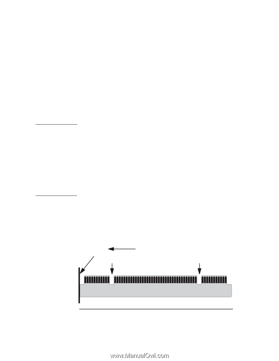
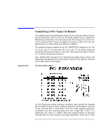
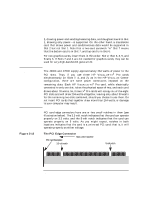
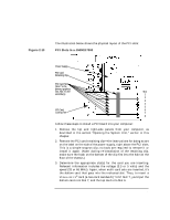
CAUTION Figure 2-12 Changing Your Computer's Hardware Configuration Installing a PCI-Type I/O Board 2, drawing power and sending/receiving data, and daughter board in Slot 1, drawing only power-is supported. On the other hand, a standalone card that draws power and sends/receives data would be supported in Slot 2 but not Slot 1. Note that a two-card sandwich "in" Slot 7 means that the bottom card is in Slot 7, and top card is in Slot 6. For non-graphics cards, insert them in this order: Slot 2, then 8, 3, 5, and finally 6. If Slots 7 and 4 are not needed for graphics cards, they can be used for very-high-bandwidth general I/O. The J5000 and J7000 supply approximately 264 watts of power to the PCI slots. Thus, if you use three HP VISUALIZE-FX6 Pro cards simultaneously (in Slots 7, 4, and 2), as in the HP VISUALIZE Center configuration, there are some power constraints imposed on the remaining slots. Each HP VISUALIZE-FX6 Pro card, while electrically connected to only one slot, takes the physical space of two, and each card draws about 78 watts. So, three FX6 Pro cards will occupy six of the eight PCI slots and will draw 234 watts altogether, leaving only about 30 watts for the remaining two slots combined, should you choose to use them. Do not insert PCI cards that together draw more than 264 watts, or damage to your computer may result. PCI card edge connectors have one or two small notches in them (see illustration below). The 3.3-volt notch indicates that the card can operate properly on 3.3 volts, and the 5-volt notch indicates that the card can operate properly on 5 volts. As you might expect, notches in both locations indicates that the card is a universal PCI card; that is, it will operate properly on either voltage. The PCI Edge Connector Back of the machine PCI Card Backplate 3.3-volt notch 5-volt notch 56 Chapter 2
-
 1
1 -
2
-
3
-
4
-
5
-
6
-
7
-
8
-
9
-
10
-
11
-
12
-
13
-
14
-
15
-
16
-
17
-
18
-
19
-
20
-
21
-
22
-
23
-
24
-
25
-
26
-
27
-
28
-
29
-
30
-
31
-
32
-
33
-
34
-
35
-
36
-
37
-
38
-
39
-
40
-
41
-
42
-
43
-
44
-
45
-
46
-
47
-
48
-
49
-
50
-
 51
51 -
 52
52 -
 53
53 -
 54
54 -
 55
55 -
 56
56 -
 57
57 -
 58
58 -
 59
59 -
 60
60 -
 61
61 -
62
-
63
-
64
-
65
-
66
-
67
-
68
-
69
-
70
-
71
-
72
-
73
-
74
-
75
-
76
-
77
-
78
-
79
-
80
-
81
-
82
-
83
-
84
-
85
-
86
-
87
-
88
-
89
-
90
-
91
-
92
-
93
-
94
-
95
-
96
-
97
-
98
-
99
-
100
-
101
-
102
-
103
-
104
-
105
-
106
-
107
-
108
-
109
-
110
-
111
-
112
-
113
-
114
-
115
-
116
-
117
-
118
-
119
-
120
-
121
-
122
-
123
-
124
-
125
-
126
-
127
-
128
-
129
-
130
-
131
-
132
-
133
-
134
-
135
-
136
-
137
-
138
-
139
-
140
-
141
-
142
-
143
-
144
-
145
-
146
-
147
-
148
-
149
-
150
-
151
-
152
-
153
-
154
-
155
-
156
-
157
-
158
-
159
-
160
-
161
-
162
-
163
-
164
-
165
-
166
-
167
-
168
-
169
-
170
-
171
-
172
-
173
-
174
-
175
-
176
-
177
-
178
-
179
-
180
-
181
-
182
-
183
-
184
-
185
-
186
-
187
-
188
-
189
-
190
-
191
-
192
-
193
-
194
-
195
-
196
-
197
-
198
-
199
-
200
-
201
-
202
-
203
-
204
-
205
-
206
-
207
-
208
-
209
-
210
-
211
-
212
 |
 |