HP Visualize J5000 hp Visualize J5000, J7000 workstations owner's guide (a4978 - Page 29
Power Cord Connectors
 |
View all HP Visualize J5000 manuals
Add to My Manuals
Save this manual to your list of manuals |
Page 29 highlights
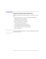
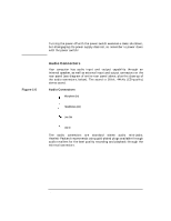
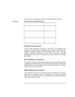
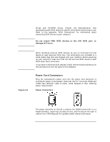
WARNING System Overview System Unit Rear Panel Connectors drives and CD-ROM drives. Consult the documentation that accompanies each SCSI device for specific information concerning its use. Refer to the appendix "SCSI Connections" for information about connecting SCSI devices to your computer. Do not attach FWD SCSI devices to the LVD SCSI port, or damage will occur. NOTE Figure 1-6 When attaching external SCSI devices, be sure to terminate the last device on each external SCSI bus. The terminators are included in a small plastic bag that was shipped with your machine. Before powering up your computer, make sure that the last external SCSI device in each SCSI chain has a terminator. If you have no external SCSI devices, install the terminators directory on the connectors on the rear panel of the computer. Power Cord Connectors Plug the workstation's power cord into the power cord connector to provide AC power to the system. Note that the HP VISUALIZE J5000 and J7000 have different types of power cords, because of their differing power requirements: Power Connectors The power connector on the left is used on the J5000 (notice that it is a keyed connector, requiring a 15-amp circuit), and the one on the right is used on the J7000 because of its greater power demand (20 amps). Chapter 1 29
-
 1
1 -
2
-
3
-
4
-
5
-
6
-
7
-
8
-
9
-
10
-
11
-
12
-
13
-
14
-
15
-
16
-
17
-
18
-
19
-
20
-
21
-
22
-
23
-
 24
24 -
 25
25 -
 26
26 -
 27
27 -
 28
28 -
 29
29 -
 30
30 -
 31
31 -
 32
32 -
 33
33 -
 34
34 -
35
-
36
-
37
-
38
-
39
-
40
-
41
-
42
-
43
-
44
-
45
-
46
-
47
-
48
-
49
-
50
-
51
-
52
-
53
-
54
-
55
-
56
-
57
-
58
-
59
-
60
-
61
-
62
-
63
-
64
-
65
-
66
-
67
-
68
-
69
-
70
-
71
-
72
-
73
-
74
-
75
-
76
-
77
-
78
-
79
-
80
-
81
-
82
-
83
-
84
-
85
-
86
-
87
-
88
-
89
-
90
-
91
-
92
-
93
-
94
-
95
-
96
-
97
-
98
-
99
-
100
-
101
-
102
-
103
-
104
-
105
-
106
-
107
-
108
-
109
-
110
-
111
-
112
-
113
-
114
-
115
-
116
-
117
-
118
-
119
-
120
-
121
-
122
-
123
-
124
-
125
-
126
-
127
-
128
-
129
-
130
-
131
-
132
-
133
-
134
-
135
-
136
-
137
-
138
-
139
-
140
-
141
-
142
-
143
-
144
-
145
-
146
-
147
-
148
-
149
-
150
-
151
-
152
-
153
-
154
-
155
-
156
-
157
-
158
-
159
-
160
-
161
-
162
-
163
-
164
-
165
-
166
-
167
-
168
-
169
-
170
-
171
-
172
-
173
-
174
-
175
-
176
-
177
-
178
-
179
-
180
-
181
-
182
-
183
-
184
-
185
-
186
-
187
-
188
-
189
-
190
-
191
-
192
-
193
-
194
-
195
-
196
-
197
-
198
-
199
-
200
-
201
-
202
-
203
-
204
-
205
-
206
-
207
-
208
-
209
-
210
-
211
-
212
 |
 |