eMachines T6528 NG3 Hardware Reference - Page 181
press the processor retention lever back into place., Place the heat sink over the processor
 |
View all eMachines T6528 manuals
Add to My Manuals
Save this manual to your list of manuals |
Page 181 highlights
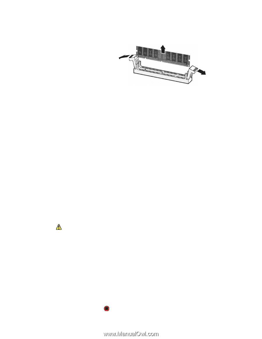
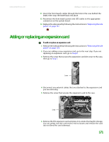
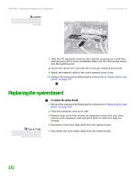
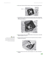
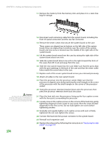
CHAPTER 13: Adding and Replacing Components www.emachines.com 11 Remove the memory from the memory slots and place it in a static-free bag for storage. Caution The heat sink has Thermal Interface Material (TIM) located on the bottom of it. Use caution when you unpack the heat sink so you do not damage the TIM. 174 12 Disconnect each remaining cable from the system board, including the front I/O panel connectors and the rear fan connector. 13 Remove the seven screws that secure the system board to the case. Three screws are aligned top-to-bottom on the left side of the system board, three are aligned top-to-bottom near the center of the system board, and one screw is located near the middle of the right side of the system board. 14 Lift the system board away from the case by raising the right side of the system board about one inch. 15 Slide the system board about one inch to the right (toward the front of the case), then lift it out and away from the case. 16 Slide the new system board into the case. Make sure that the ports align with the port openings in the back of the case and that the seven screw holes match the screw holes in the case. 17 Replace each of the seven system board screws you removed previously. 18 Attach all cables to the new system board. 19 Place the processor into the processor socket. Make sure that the processor is aligned correctly by matching the small triangle on the corner of the processor with the small triangle on the corner of the processor socket. 20 Swing the processor retention bracket down onto the processor, then press the processor retention lever back into place. 21 Place the heat sink over the processor, lining up the four captive screws with the four posts surrounding the processor. 22 Loosely screw in the captive screws on the corners of the heat sink, gently tightening diagonal screws (screw in one screw, then the screw located diagonally to the first screw). Do not fully tighten one screw before tightening another. 23 Gradually and equally tighten each captive screw until each is firmly tightened. Do not over-tighten the screws. 24 Connect the heat sink fan's power connector to the system board. 25 Reinstall each expansion card. 26 Replace the side panel by following the instructions in "Replacing the side panel" on page 157.
-
 1
1 -
2
-
3
-
4
-
5
-
6
-
7
-
8
-
9
-
10
-
11
-
12
-
13
-
14
-
15
-
16
-
17
-
18
-
19
-
20
-
21
-
22
-
23
-
24
-
25
-
26
-
27
-
28
-
29
-
30
-
31
-
32
-
33
-
34
-
35
-
36
-
37
-
38
-
39
-
40
-
41
-
42
-
43
-
44
-
45
-
46
-
47
-
48
-
49
-
50
-
51
-
52
-
53
-
54
-
55
-
56
-
57
-
58
-
59
-
60
-
61
-
62
-
63
-
64
-
65
-
66
-
67
-
68
-
69
-
70
-
71
-
72
-
73
-
74
-
75
-
76
-
77
-
78
-
79
-
80
-
81
-
82
-
83
-
84
-
85
-
86
-
87
-
88
-
89
-
90
-
91
-
92
-
93
-
94
-
95
-
96
-
97
-
98
-
99
-
100
-
101
-
102
-
103
-
104
-
105
-
106
-
107
-
108
-
109
-
110
-
111
-
112
-
113
-
114
-
115
-
116
-
117
-
118
-
119
-
120
-
121
-
122
-
123
-
124
-
125
-
126
-
127
-
128
-
129
-
130
-
131
-
132
-
133
-
134
-
135
-
136
-
137
-
138
-
139
-
140
-
141
-
142
-
143
-
144
-
145
-
146
-
147
-
148
-
149
-
150
-
151
-
152
-
153
-
154
-
155
-
156
-
157
-
158
-
159
-
160
-
161
-
162
-
163
-
164
-
165
-
166
-
167
-
168
-
169
-
170
-
171
-
172
-
173
-
174
-
175
-
 176
176 -
 177
177 -
 178
178 -
 179
179 -
 180
180 -
 181
181 -
 182
182 -
 183
183 -
 184
184 -
 185
185 -
 186
186 -
187
-
188
-
189
-
190
-
191
-
192
-
193
-
194
-
195
-
196
-
197
-
198
-
199
-
200
-
201
-
202
-
203
-
204
-
205
-
206
-
207
-
208
-
209
-
210
-
211
-
212
-
213
-
214
 |
 |