Netgear D7800 User Manual - Page 16
USB Ports on the Left Panel, eSATA Port on the Right Panel, LED Off/On switch, LED Off/On
 |
View all Netgear D7800 manuals
Add to My Manuals
Save this manual to your list of manuals |
Page 16 highlights
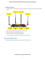
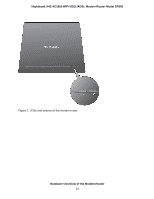
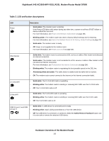
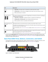
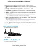
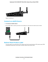
Nighthawk X4S AC2600 WiFi VDSL/ADSL Modem Router Model D7800 In addition to the antennas, viewed from left to right, the back panel contains the following components: • LED Off/On switch. Move the LED Off/On switch to to the Off position to turn off all LEDs, except for the Power LED. • Reset button. For information about using the Reset button, see Use the Reset Button on page 222. • Ethernet LAN ports. Four Gigabit Ethernet RJ-45 LAN ports to connect the modem router to LAN devices. These ports are colored yellow. • Internet port. One Gigabit Ethernet RJ-45 WAN port to connect the modem router to a fiber or cable modem. This port is colored red. Note You can use either the Internet port or the DSL port for WAN connectivity. • DSL port. One RJ-11 DSL port for connecting the modem router to an ADSL or VDSL line. This port is colored gray. In the previous figure, the DSL port is marked VDSL. Note You can use either the DSL port or the Internet port for WAN connectivity. • DC power connector. Connect the power adapter that came in the product package to the DC power connector. • Power On/Off button. Press the Power On/Off button to provide power to the modem router. USB Ports on the Left Panel Two 3.0 USB ports are located on the left panel. Figure 4. USB ports eSATA Port on the Right Panel An eSATA port is located on the right panel. Hardware Overview of the Modem Router 16
-
 1
1 -
2
-
3
-
4
-
5
-
6
-
7
-
8
-
9
-
10
-
 11
11 -
 12
12 -
 13
13 -
 14
14 -
 15
15 -
 16
16 -
 17
17 -
 18
18 -
 19
19 -
 20
20 -
 21
21 -
22
-
23
-
24
-
25
-
26
-
27
-
28
-
29
-
30
-
31
-
32
-
33
-
34
-
35
-
36
-
37
-
38
-
39
-
40
-
41
-
42
-
43
-
44
-
45
-
46
-
47
-
48
-
49
-
50
-
51
-
52
-
53
-
54
-
55
-
56
-
57
-
58
-
59
-
60
-
61
-
62
-
63
-
64
-
65
-
66
-
67
-
68
-
69
-
70
-
71
-
72
-
73
-
74
-
75
-
76
-
77
-
78
-
79
-
80
-
81
-
82
-
83
-
84
-
85
-
86
-
87
-
88
-
89
-
90
-
91
-
92
-
93
-
94
-
95
-
96
-
97
-
98
-
99
-
100
-
101
-
102
-
103
-
104
-
105
-
106
-
107
-
108
-
109
-
110
-
111
-
112
-
113
-
114
-
115
-
116
-
117
-
118
-
119
-
120
-
121
-
122
-
123
-
124
-
125
-
126
-
127
-
128
-
129
-
130
-
131
-
132
-
133
-
134
-
135
-
136
-
137
-
138
-
139
-
140
-
141
-
142
-
143
-
144
-
145
-
146
-
147
-
148
-
149
-
150
-
151
-
152
-
153
-
154
-
155
-
156
-
157
-
158
-
159
-
160
-
161
-
162
-
163
-
164
-
165
-
166
-
167
-
168
-
169
-
170
-
171
-
172
-
173
-
174
-
175
-
176
-
177
-
178
-
179
-
180
-
181
-
182
-
183
-
184
-
185
-
186
-
187
-
188
-
189
-
190
-
191
-
192
-
193
-
194
-
195
-
196
-
197
-
198
-
199
-
200
-
201
-
202
-
203
-
204
-
205
-
206
-
207
-
208
-
209
-
210
-
211
-
212
-
213
-
214
-
215
-
216
-
217
-
218
-
219
-
220
-
221
-
222
-
223
-
224
-
225
-
226
-
227
-
228
-
229
-
230
-
231
-
232
-
233
-
234
-
235
-
236
-
237
-
238
-
239
-
240
-
241
-
242
-
243
-
244
-
245
-
246
-
247
-
248
-
249
-
250
-
251
-
252
-
253
-
254
-
255
-
256
-
257
-
258
-
259
-
260
-
261
-
262
-
263
-
264
-
265
-
266
-
267
-
268
-
269
-
270
-
271
-
272
-
273
-
274
-
275
-
276
-
277
-
278
-
279
-
280
-
281
-
282
-
283
-
284
-
285
-
286
-
287
-
288
-
289
-
290
-
291
-
292
-
293
-
294
-
295
-
296
-
297
-
298
-
299
 |
 |